Throttle Application Manual
Disclaimer
Proprietary Information: This manual contains proprietary information belonging to Emsiso d.o.o. The text and graphics included are for illustration and reference purposes only. Specifications are subject to change without notice.
Scope of Application: The Throttle Application is designed for integration with emDrive systems. Users should ensure compatibility with their specific hardware and software configurations.
User Responsibility: Proper installation, configuration, and operation of the Throttle Application require technical expertise. Users must adhere to all safety guidelines and operational instructions provided in this manual.
Updates and Revisions: Emsiso d.o.o. reserves the right to modify the product and manual without prior notice. Users are encouraged to consult the latest version of the manual for up-to-date information.
Liability Disclaimer: Emsiso d.o.o. assumes no liability for damages resulting from the use or misuse of the Throttle Application, including but not limited to personal injury, equipment damage, or financial loss.
By using the Throttle Application, you acknowledge that you have read, understood, and agreed to these terms and conditions
1. Introduction
1.1 Overview
The Throttle application allows the user to implement a simple throttle control directly on the emDrive. Input devices can be connected directly to the emDrive and mapped to the throttle application. The application calculates the desired output based on these inputs and passes it to motor control. The output can be used as either a torque input or a speed input in the motor controller, depending on which CANOpen object the output is mapped to.
1.2 Features
The Throttle application supports the following features:
- Throttle Module
Functionality: Calculates the desired output based on mapped input and configuration parameters.
Capabilities: Can be configured as unidirectional or bidirectional. - Brake Module
Functionality: Calculates the desired brake torque based on mapped input and configuration parameters.
Capabilities: Unidirectional only, with brake torque always in the opposite direction to motor rotation.If the desired output is speed, the brake should be disabled as this module is intended to be used for torque control.
- Pump Control Module
Functionality: Controls the pump, turning it on or off depending on motor and drive temperature. - Precharge Module
Functionality: Manages the precharge process at startup. - DC-DC Turn on Delay Module
Functionality: Delays the activation of the DC-DC converter after startup to ensure controlled power application. - SOC Monitoring Module
Functionality: Monitors the State of Charge (SOC) of the battery.
Capabilities: Reduces the maximum allowed torque when SOC is below a specified threshold.Requires an external Battery Management System (BMS) to operate correctly.
- Charging Detection Module
Functionality: Detects when the battery is charging and disables the drive during the charging process. - Input Mapping
Functionality: Allows certain inputs to the throttle application to be mapped to CAN objects on the emDrive.
All throttle application features can be independently enabled or disabled (except the brake module, which requires the throttle module to be enabled). This is done by setting the Thr1_Enable CAN objects of the throttle application as detailed in Table 1.
| Object Name |
Object Index |
Object Subindex |
Description | Unit |
|
Thr1_Gen__Enable |
0x4010 | 0x01 |
Enables the throttle application: 1 – enabled (must be enabled for any modules to work) |
/ |
| Thr1_Enable__Throttle | 0x4011 |
0x01 |
Enables the throttle module: 0 – disabled |
Bit |
| Thr1_Enable__Brake | 0x4011 | 0x02 |
Enables the brake module: 0 – disabled |
Bit |
| Thr1_Enable__Pump | 0x4011 | 0x03 |
Enables the pump control module: 1 – enabled |
Bit |
| Thr1_Enable__Precharge | 0x4011 | 0x04 |
Enables the precharge module: 0 – disabled |
Bit |
| Thr1_Enable__DC_DC | 0x4011 | 0x05 |
Enables the DC-DC turn on delay module: 0 – disabled |
Bit |
| Thr1_Enable__SOC | 0x4011 | 0x06 |
Enables the SOC monitoring module: 0 – disabled |
Bit |
| Thr1_Enable__ChargingDetect | 0x4011 | 0x07 |
Enables the charging detection module: 0 – disabled |
Bit |
2. Input and Output mapping
Input and output mapping for the Throttle application is managed using the Thr1_Obj object, which stores the CANOpen indexes and subindexes of the inputs and outputs mapped to the Throttle application variables. You can remap any variable to a different input by writing the CANOpen index and subindex of the new input to the corresponding Thr1_Obj sub-object.
The following table outlines the object mapping parameters for the Throttle application. Each object in the table represents a specific function or control point within the application, and the corresponding CANOpen index and subindex define where these objects are located in the CANOpen network. By configuring these parameters, users can tailor the Throttle application to their specific needs, ensuring precise control and monitoring of various functions.
By correctly configuring these object mappings, users can ensure that the Throttle application communicates accurately with the various inputs and outputs connected to the emDrive. This flexibility allows for precise control of throttle, brake, pump, and other critical functions, enhancing the overall performance and reliability of the system.
| Object Name |
Object Index |
Object Subindex |
Description | Unit |
| Thr1_Obj__AppControl | 0x4012 | 0x01 |
Address of CAN object where commands are sent to application |
Obj |
| Thr1_Obj__AppState | 0x4012 | 0x02 |
Address of CAN object where application state is saved |
Obj |
| Thr1_Obj__ThrottleInput | 0x4012 | 0x03 | Address of CAN object with throttle input | Obj |
| Thr1_Obj__ThrottleFWD_DIvalue | 0x4012 | 0x04 |
Address of CAN object to forward switch input |
Obj |
| Thr1_Obj__ThrottleREW_DIvalue | 0x4012 | 0x05 |
Address of CAN object to reverse switch input |
Obj |
| Thr1_Obj__TargetObj | 0x4012 | 0x06 |
Address of CAN object where output of throttle application is written |
Obj |
| Thr1_Obj__BatValid | 0x4012 | 0x07 |
Address of CAN object which stores BMS status. |
Obj |
| Thr1_Obj__BatSOC | 0x4012 | 0x08 |
Address of CAN object which stores battery SOC in percentage |
Obj |
| Thr1_Obj__BatState | 0x4012 | 0x09 |
Address of CAN object which stores battery state |
Obj |
| Thr1_Obj__ChargingDetectDIvalue | 0x4012 | 0x0A |
Address of CAN object which shows if charging is detected. If not 0 throttle application considers battery to be charging. |
Obj |
| Thr1_Obj__Pump1EnableDO | 0x4012 |
0x0B |
Address of CAN object with main pump enable control - active always when power stage is enabled |
Obj |
| Thr1_Obj__Pump2EnableDO | 0x4012 | 0x0C |
Address of CAN object with cooling pump enable control |
Obj |
| Thr1_Obj__CoolingInputTemperature1 | 0x4012 | 0x0D |
Address of CAN object with temperature input 1 (default bridge heatsink temp) |
Obj |
| Thr1_Obj__CoolingInputTemperature2 | 0x4012 | 0x0E |
Address of CAN object with temperature input 2 (default motor temp) |
Obj |
| Thr1_Obj__DCDCenableDO | 0x4012 | 0x0F |
Address of CAN object with DC-DC enable control |
Obj |
| Thr1_Obj__BuzzerDO1 | 0x4012 | 0x10 |
Address of CAN object with buzzer high side enable control |
Obj |
| Thr1_Obj__BuzzerDO2 | 0x4012 | 0x11 |
Address of CAN object with buzzer low side enable control |
Obj |
| Thr1_Obj__BrakeInput | 0x4012 | 0x12 | Address of CAN object with brake input | Obj |
| Thr1_Obj__RPM_in | 0x4012 | 0x13 | Address of CAN object with RPM data | Obj |
| Thr1_Obj__MainRelayEnableDO | 0x4012 | 0x14 |
Address of CAN object with main relay enable control |
Obj |
| Thr1_Obj__PrechargeRelayEnableDO | 0x4012 | 0x15 |
Address of CAN object with precharge relay enable control |
Obj |
| Thr1_Obj__PrechargeDC_voltage | 0x4012 | 0x16 |
Address of CAN object with measured voltage during precharge procedure |
Obj |
| Thr1_Obj__PrechargeBatteryVoltage | 0x4012 | 0x17 |
Precharge voltage reported by battery. Set to 0 if not available/used. [obj] |
Obj |
2.1 Examples
2.1.1. Configuring an object to be used in the application (e.g. for Thr1_Obj__ThrottleInput)
All mapping of object to the application are done in the same way. For relays (digital outputs), switches (digital inputs), torque & velocity reference,... The main point is to show that you need to combine index and subindex of the object you want to use in your throttle application.
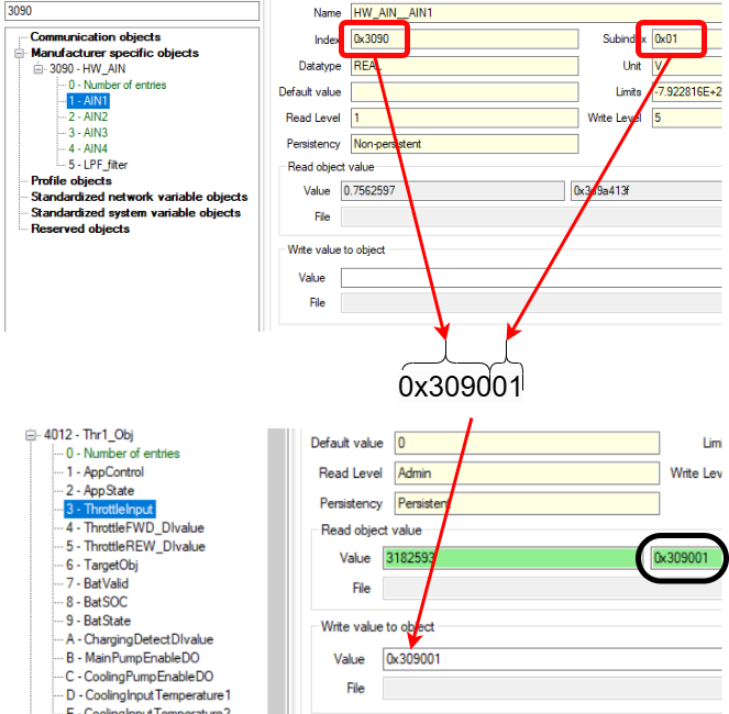
For example, to map the throttle voltage input to the emDrive analog input 1 (which has a CANOpen object HW_AIN_AIN1 with index 0x3090 and subindex 0x01 as shown in the picture below), you would write 0x309001 to Thr1_Obj__ThrottleVoltage.
To verify that the correct value has been written, check the HEX value indicated by the black circle (black circle).
3. How to Use Each Module
3.1 Initial Setup Assumptions
It is assumed that the user has already calibrated the angle sensor, and that all other emDrive parameters for the motor and regulation have been properly configured.
Before using any module, the CANOpen object Thr1_Gen__Enable (index 0x4010, subindex 0x01) must be enabled by writing a value of 1.
0x4010 0x01 - Thr1_Gen__Enable = 1
3.2 Precharge Module
The Precharge module limits the charging current of the emDrive capacitors by activating the precharge relay switch before the main relay switch is engaged. The precharge relay switch has a resistor connected in series, which limits the current during the capacitor charging phase.
Note that the main and precharge relay switches are not integrated within the emDrive and must be provided externally. For more details, refer to section 5.4 of the emDrive user manual.
For readability and clarity, the following abbreviations are used:
- The precharge relay switch refers to
Thr1_Obj__PrechargeRelayEnableDO - The main relay switch refers to
Thr1_Obj__MainRelayEnableDO
The sequence begins with the activation of the precharge relay switch. After the duration specified by the Thr1_Precharge__PrechargeTime parameter (default is 2 seconds), the drive voltage is checked. If the voltage does not exceed the threshold set by the Thr1_Precharge__MinDC_Voltage parameter, an error state is reported. If the voltage is above this threshold, the main relay switch is activated. Finally, after the time specified by the Thr1_Precharge__DelayBeforePrechargeOff parameter has elapsed, the precharge relay switch is turned off, and the run state is set to true, activating the throttle and brake functionality. Additionally, we have a diagram illustrating the above functionality. It is assumed that after the precharge time, the DC voltage exceeds the set threshold, thus no error state is encountered.

To set this module you have to set all of the objects in table 3 and also use the correct mapping for Thr1_Obj__PrechargeRelayEnableDO and Thr1_Obj__MainRelayEnableDO.
| Object Name |
Object Index |
Object Subindex |
Description | Unit |
| Thr1_Precharge__PrechargeTime | 0x4016 | 0x01 | Time to wait after the precharge relay switch is activated before checking the voltage | s |
| Thr1_Precharge__DelayBeforePrechargeOff | 0x4016 | 0x02 | Time to wait before precharge relay switch is deactivated after the main relay switch has been activated |
s |
| Thr1_Precharge__MinDC_Voltage | 0x4016 | 0x03 | Minimum voltage that must be present on drive capacitors in order to not enter error state |
V |
| Thr1_Precharge__AllowedVoltageDifference | 0x4016 | 0x04 | In case battery voltage is provided, this is maximum difference allowed between battery voltage and DC link voltage after precharge time to not trigger precharge error | V |
You can also verify whether the precharge completed successfully or if an error occurred using the precharged module signals.
| Object Name |
Object Index |
Object Subindex |
Description | Unit |
| Thr1_Precharge__Run | 0x4016 | 0x05 | Set to 1 when precharge is successfully finished | bit |
| Thr1_Precharge__Err | 0x4016 | 0x06 | Set to 1 if there was an error during precharge | bit |
The module also allows configuration of the precharge module to compare the DC link voltage measured on the inverter with the actual voltage of the battery. It will turn on the main relay only when the voltage difference is less than the threshold specified by Thr1_Precharge__AllowedVoltageDifference (this needs to happen before the Thr1_Precharge__PrechargeTime). An example of this configuration can be found under "Precharge Example 2".

3.2.1 Examples
- Precharge example 1
Description:
In this example, we will use the precharge module. For this, we need two relays: the main relay and the precharge relay. We also need to determine the voltage threshold for activating the main relay and the correct timings, which are described in Section 3.2.
Relay Connections
Main Relay: Connected to HW_LS1 (Index: 0x30A0, Subindex: 0x02)
Precharge Relay: Connected to HW_LS2 (Index: 0x30A1, Subindex: 0x02)
Voltage Measurement
The voltage will be measured using the inverter, which is the standard method (0x3101 0x07 Udc).
Timings
Precharge Time: 2 seconds
Time After Precharge Relay Turns Off: 0.5 seconds
Voltage Threshold
The voltage threshold for activating the main relay is 24V.
Objects to set:
-
- Enable Throttle Application:
0x4010 0x01 - Thr1_Gen__Enable = 1 - Enable the Precharge Module:
Enable the Precharge Module by setting the corresponding flag in the throttle general object0x4011 Thr1_Enable__Prechargeto 1.0x4011 0x04 Precharge = 1 - Map Objects to the Application:
Choose the proper digital outputs to control the main relay and precharge relay:
e.g:
As per description we have the main relay connected to HW_LS1 and the precharge relay connected to HW_LS2. The object indexes are as follows:HW_LS1 = 0x30A0 0x02HW_LS2 = 0x30A1 0x02
We set the following:0x4012 0x14 MainRelayEnableDO = 0x30A0020x4012 0x15 PrechargeRelayEnableDO = 0x30A102
It is recommended to use the default voltage measurement (0x3101 0x07 Udc), unless a different object mapping is required0x4012 0x16 PrechargeDC_Voltage = 0x310107
- Enable Throttle Application:
- Configure the Precharge Module:
Set the precharge time:0x4016 0x01 PrechargeTime = 2
Set the time after the precharge relay is turned off:0x4016 0x02 DelayBeforePrechargeOff = 0.5
Set the minimum voltage that must be present:0x4016 0x03 MinDC_Voltage = 24 - Save and Reset:
Save the settings (Ctrl+S) and perform a reset.
Switch to operational mode.
Test
Enable auto start if everything works correctly (inverter will always go to operational mode after reset).0x3000 0x03 AutoStart = 1
- Precharge example 2
Description:
In this example, we will use the precharge module, to enable the min relay when the difference between the DC - link on the inverter and the battery voltage is less than the threshold set in Thr1_Precharge__AllowedVoltageDifference
For this example, you need to first finish the Precharge example 1 and then continue with the following steps.
First you need to use the PDOs to get the value of the battery and map it to one of the 0x3020 - General_Purpose objects.
In this example the voltage value of the battery is sent to 0x3020 0x09 - General_Purpose__gen1_32bit.
First you need to map the object where the value of the battery is stored:0x4012 0x17 - PrechargeBatteryVoltage = 0x302009
Next you need to set allowed difference between DC-link that is measured on the inverter and the voltage of the battery.
Lets assume that the allowable voltage difference is 10V.0x4016 0x04 - AllowedVoltageDifference = 10V
If the actual voltage difference is more than 0x4016 0x04 - AllowedVoltageDifference = 10V, after the period specified in Thr1_Precharge__PrechargeTime an error is raised.
3.3 Throttle module
The throttle module is responsible for calculating the desired output value based on the given input voltage. It provides features such as short to ground and short to power supply detection, reading forward and reverse switches, rate-limiting the output, and disabling the throttle when the brake is active. Below is a detailed guide on the state diagram and parameter settings for the throttle module.
| Object Name |
Object Index |
Object Subindex |
Description | Unit |
| Thr1_Throttle__ZeroValue | 0x4013 |
0x01 |
At this input value output is zero. | V |
| Thr1_Throttle__ZeroDeadBand | 0x4013 | 0x02 | Defines how large zero dead band is | V |
| Thr1_Throttle__EnableDeadBand | 0x4013 | 0x03 | Defines how large enable dead band is. Should be less or equal to Thr1_Throttle__ZeroDeadBand value. |
V |
| Thr1_Throttle__MaxInput | 0x4013 | 0x04 | At this input value output is at maximum value defined in Thr1_Throttle__OutFullPositive |
V |
| Thr1_Throttle__MinInput | 0x4013 | 0x05 | At this input value output is at minimum value defined in Thr1_Throttle__OutFullNegative |
V |
| Thr1_Throttle__NonValidMax | 0x4013 | 0x06 | Any input value greater than this will put throttle module into error state |
V |
| Thr1_Throttle__NonValidMin | 0x4013 | 0x07 | Any input value lesser than this will put throttle module into error state |
V |
| Thr1_Throttle__Progressive | 0x4013 | 0x08 | Determines how the output changes in relationship to the input between zero value and max value |
/ |
| Thr1_Throttle__Invert | 0x4013 | 0x09 | Inverts output | Bit |
| Thr1_Throttle__RateLimit | 0x4013 | 0x0A | Limits how fast output can change. | 1/s |
| Thr1_Throttle__OutFullPositive | 0x4013 | 0x0B | Output when input reaches max input defined in Thr1_Throttle__MaxInput |
/ |
| Thr1_Throttle__OutFullNegative | 0x4013 | 0x0C | Output when input reaches min input defined in Thr1_Throttle__MinInput |
/ |
| Thr1_Throttle__OutStartPositive | 0x4013 | 0x0D | Starting output value when throttle is no longer 0, for positive throttle values | / |
| Thr1_Throttle__DisableAtBrake | 0x4013 | 0x0E | If set to 1, the throttle command is disabled (ramped down to 0) when the brake is activated; otherwise, the brake demand is subtracted from the throttle demand | Bit |
| Thr1_Throttle__WaitBeforeBridgeDisable | 0x4013 | 0x0F | Time to wait after throttle is disabled before bridge is disabled | s |
| Thr1_Throttle__WaitAfterStart | 0x4013 | 0x10 | How long to wait after startup before operational state is entered |
s |
| Thr1_Throttle__IsNegativeBrake | 0x4013 | 0x11 | If set to 1, negative throttle will be treated as brake | / |
| Thr1_Throttle__OutStartNegative | 0x4013 | 0x1A | Starting output value when throttle is no longer 0, for negative throttle values | / |
| Thr1_Throttle__SkipInitWaitForSpeedDrop | 0x4013 | 0x1B | If set to 1, wait for speed drop will be skipped during initialization | Bit |
| Object Name |
Object Index |
Object Subindex |
Description | Unit |
| Thr1_Throttle__Input | 0x4013 | 0x12 | Input from throttle | / |
| Thr1_Throttle__OutNorm | 0x4013 | 0x13 | Normalized throttle output (-1 full negative, 1 full positive) |
/ |
| Thr1_Throttle__Out | 0x4013 | 0x14 | Throttle output in system units | / |
| Thr1_Throttle__TotalOut | 0x4013 | 0x15 | Sum of throttle and brake in system units | / |
| Thr1_Throttle__Enabled | 0x4013 | 0x16 | If throttle is out of centre position for EnableDeadBand - power stage enabled | Bit |
| Thr1_Throttle__State | 0x4013 | 0x17 |
State of throttle state machine: |
/ |
| Thr1_Throttle__Err | 0x4013 | 0x18 | If throttle input is outside NonValidMax or NonValidMin | Bit |
| Thr1_Throttle__ErrCode | 0x4013 | 0x19 | Flag bits for different errors. 0x01 -> throttle, 0x02 -> precharge, 0x04 -> App/drive low level, 0x08 -> brake |
/ |
3.3.1 State Diagram
The state diagram for the throttle module consists of several states and transitions, ensuring the correct operation and safety of the system.
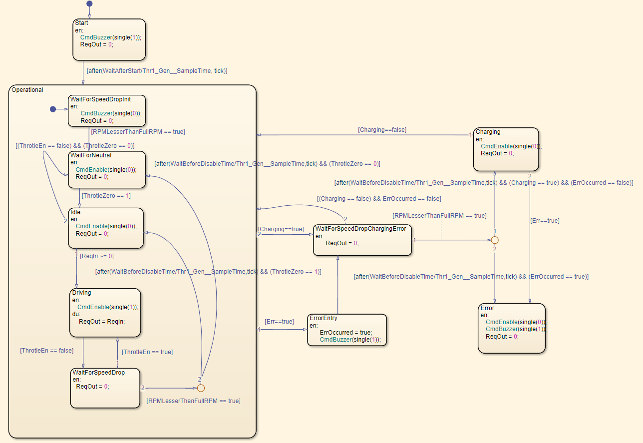
Startup State
- Buzzer Activation: Upon system start, the buzzer is activated if an external buzzer is connected.
- Wait Time: The system waits for the duration specified by the parameter Thr1_Throttle__WaitAfterStart to complete the startup.
- Error Check: If an error is detected during startup, the system transitions directly to the Error State.
Operational State
- Buzzer Deactivation: The buzzer is disabled upon entering the operational state.
- RPM Check: The system waits for the RPM to drop to 0, if it is not already there.
- Bridge Disable: The bridge is disabled, and the system waits for the throttle to be set to zero.
Idle State
- Idle Mode: The system enters the Idle State, waiting for the input to move out of the zero position.
Driving State
- Throttle Enabled: If the input moves out of the zero position and the throttle is enabled, the system transitions to the Driving State.
- Bridge Enable: The bridge is enabled, and the output is forwarded to motor control.
WaitForNeutral State
- Throttle Disabled: If the throttle is disabled and the output moves out of the zero position, the system returns to the WaitForNeutral State.
WaitForSpeedDrop State
- Output Set to 0: When the throttle is disabled during the Driving State (either due to Thr1_Enable__Throttle being set to 0, input within the disable dead band, or outside allowed values), the system enters the WaitForSpeedDrop State.
- RPM Check: The output is set to 0, but the bridge remains enabled until the RPM drops below the value specified by Thr1_Brake__Full_RPM.
- Wait Time: The system waits for the time configured in Thr1_Throttle__WaitBeforeBridgeDisable.
- State Transition: The state changes to Idle or WaitForNeutral based on whether the input is at zero or not.
Charging State
- RPM Drop: If charging is detected during the operational state, the system waits for the RPM to drop.
- Bridge Disable: The system moves to the Charging State, where the bridge is disabled.
- Return to Operational: When charging is no longer detected, the system returns to the operational state.
Error State
- Error Detection: If an error is detected in any state, the system transitions to the Error State.
- Bridge Disable: The bridge is disabled, and the buzzer is activated.
- RPM Check: In case of an error during the operational state, the system waits for the RPM to drop before disabling the bridge.
- Priority to Error State: If both charging and an error are detected simultaneously, the system prioritizes transitioning to the Error State.
- System Reset: There is no automatic recovery from the Error State; the system must be manually reset.
3.3.2 Input to Output Transformation
The input to output transformation converts the input voltage of the analog input to output torque, which is forwarded to motor control if the throttle is enabled. The basic transformation is illustrated in the graph below.

- Thr1_Throttle__ZeroValue: Defines the zero point of the input.
- Thr1_Throttle__ZeroDeadBand: Defines the dead band around the zero point. While the input voltage is within this dead band, the output remains zero.
- Thr1_Throttle__MinInput: Minimum valid input voltage.
- Thr1_Throttle__MaxInput: Maximum valid input voltage.
- Thr1_Throttle__OutFullPositive: Maximum positive output torque.
- Thr1_Throttle__OutFullNegative: Maximum negative output torque.
- Thr1_Throttle__NonValidMin: Minimum input voltage considered valid.
- Thr1_Throttle__NonValidMax: Maximum input voltage considered valid.
The transformation includes the following regions:
-
Zero Dead Band:
- Defined by
Thr1_Throttle__ZeroValueandThr1_Throttle__ZeroDeadBand. - Output remains zero when input voltage is within the dead band.
- Defined by
-
Positive Throttle Region:
- From the end of the dead band to
Thr1_Throttle__MaxInput, the output rises in the positive direction from 0 toThr1_Throttle__OutFullPositive. - Output is calculated as , where is the normalized output (0 at 0 and 1 at
Thr1_Throttle__OutFullPositive), is the normalized input (0 at the edge of the dead band and 1 atThr1_Throttle__MaxInput), and is the parameterThr1_Throttle__Progressive, which ranges between 0.3 and 3. The default value for is 1, indicating a linear growth of output torque.
- From the end of the dead band to
-
Negative Throttle Region:
- From the end of the dead band to
Thr1_Throttle__MinInput, the output falls in the negative direction. - Output is calculated as y=−∣x∣a
- From the end of the dead band to
-
Constant Max Throttle Region:
- Between
Thr1_Throttle__MaxInputandThr1_Throttle__NonValidMax, the output remains at maximum positive torque. - Between
Thr1_Throttle__MinInputandThr1_Throttle__NonValidMin, the output remains at maximum negative torque. - If the input value increases beyond
Thr1_Throttle__NonValidMaxor decreases beyondThr1_Throttle__NonValidMin, the output torque is set to 0 and the throttle module enters the error state.
- Between
This transformation ensures that the throttle application accurately converts the input voltage into the appropriate output for motor control, with safeguards in place to handle invalid input values and prevent unintended behaviour.
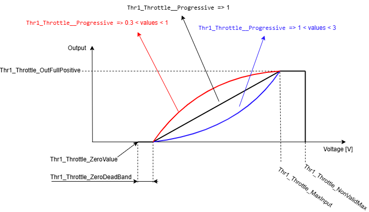
3.3.2.1 Progressive
The following chart illustrates how the throttle output changes based on different values of the Thr1_Throttle__Progressive parameter. This parameter modifies the response curve of the throttle, allowing for either a more gradual or more aggressive acceleration profile.
- Black Curve: Represents a linear throttle response where
Thr1_Throttle__Progressiveis set to 1. In this case, the output increases proportionally to the input. - Red Curve: Shows a concave transformation where
Thr1_Throttle__Progressiveis set to a value between 0.3 and 1. This setting results in a more responsive output at low throttle inputs, making the vehicle more reactive to small changes in input. - Blue Curve: Represents a convex transformation where
Thr1_Throttle__Progressiveis set to a value between 1 and 3. This setting provides a smoother and less sensitive response at lower inputs, allowing for finer control before reaching full throttle.
Understanding the Impact of Progressive Values
- When
Thr1_Throttle__Progressive< 1, the initial throttle response is stronger, and the output rises quickly at lower input values. - When
Thr1_Throttle__Progressive= 1, the response remains linear. - When
Thr1_Throttle__Progressive> 1, the output starts increasing more gradually, providing finer control in the lower range.
By adjusting this parameter, the response can be fine-tuned so that the throttle behaviour matches specific application needs.
3.3.3 Other throttle module functions
Enable dead band
Enable Dead Band functions similarly to Zero Dead Band. However, instead of setting the throttle output to 0, it disables the driver bridge when the input is less than a specified distance from the zero point. This distance is determined by the Enable Dead Band threshold. To disable Enable Dead Band, set its value to 0.
Ensure this threshold is always smaller than the Zero Dead Band threshold to prevent unusual behaviour.
Disable at brake
When the parameter 0x4013 0x0E DissableAtBrake is set to 1, the throttle module output is set to zero whenever the brake is active. This means that as soon as the brake is applied, the emDrive system will start braking immediately, regardless of the throttle input.
When the parameter 0x4013 0x0E DissableAtBrake is set to 0, the throttle and brake outputs are combined before being sent to motor control. In this case, the emDrive system will only start braking if the brake output is greater than the throttle output.
Rate limit
The rate limit controls how quickly the output can change in response to changes in the input (Higher the number, faster the change). This is determined by the parameter 0x4013 0x0A RateLimit.
When the input changes from 0 to 1 (works on normed value), the output will change from 0 to 1 in 1 / RateLimit seconds.
Output of throttle at zero value
If the application needs a specific output (not zero) to be set at zero position of a potentiometer 0x4013 0x01 ZeroValue, the object 0x4013 0x0D OutStartPositive can be set to achieve this functionality. This will be presented in Throttle example 4.
With this feature the 0x4013 - Thr1_Throttle__EnableDeadBand, should be disabled

3.3.4 Examples
- Throttle example 1
Description:
Monodirectional throttle using only one analog input.
In this example, we will use a potentiometer as our throttle input. Our goal is to control the motor in velocity mode, ranging from 0 to 100 RPM.
Throttle Input Details
Potentiometer: Used as the throttle input. Connected to AIN3 = 0x3090 0x03
Voltage and RPM Control
Error Condition: If the voltage from the potentiometer is lower than 0.2V or higher than 4.8V, an error will occur (indicating a possible short or broken connection).
0 RPM: At 0.5V, the motor should run at 0 RPM.
100 RPM: At 4.5V, the motor should run at the maximum speed of 100 RPM.
Objects to set:
-
- Enable Throttle Application:
0x4010 0x01 - Thr1_Gen__Enable = 1 - Enable the Throttle Module:
Use the throttle general object0x4011 Thr1_Enableto enable the proper module.0x4011 0x01 Throttle = 1 - Map Objects to the Application:
Choose the reference value to control (velocity or torque) and map analog/digital inputs and outputs.
To control velocity:0x4012 0x06 TargetObj = 0x301005
To control torque:0x4012 0x06 TargetObj = 0x301004
Set the control mode (0 for torque, 1 for velocity):0x3100 0x01 ControlMode = 0 or 1
Define the analog throttle input (potentiometer on AIN3):0x4012 0x03 ThrottleInput = 0x309003 - Configure the Throttle Module:
Set the throttle voltage parameters as explained in Section 4.2:0x4013 0x01 ZeroValue = 0.50x4013 0x04 MaxInput = 4.50x4013 0x05 MinInput = 0.50x4013 0x06 NonValidMax = 4.80x4013 0x07 NonValidMin = 0.2
Set the maximum and minimum TorqueRef or VelocityRef:
In this example we will use max = 100rpm and min = 0rpm0x4013 0x0B OutFullPositive = 1000x4013 0x0C OutFullNegative = 0 - Save and Reset:
Save the settings (Ctrl+S) and perform a reset.
Switch to operational mode.
Test
Enable auto start if everything works correctly (inverter will always go to operational mode after reset).0x3000 0x03 AutoStart = 1
- Enable Throttle Application:
- Throttle example 2
Description:
In this example, we will use the same potentiometer as in Throttle Example 1. The main difference is that this setup allows for bidirectional control of the throttle. Here’s how it works:
- At 2.5V, the motor will be at 0 RPM.
- At 4.5V, the motor will run at 100 RPM.
- At 0.5V, the motor will run at -100 RPM (in reverse).
This setup enables you to control the motor speed and direction using a single analog input.
Objects to set:
-
- Same as example "Throttle example 1"
- Same as example "Throttle example 1"
- Same as example "Throttle example 1"
- Configure the Throttle Module:
Set the throttle voltage parameters as explained in Section 4.2:0x4013 0x01 ZeroValue = 2.50x4013 0x04 MaxInput = 4.50x4013 0x05 MinInput = 0.50x4013 0x06 NonValidMax = 4.80x4013 0x07 NonValidMin = 0.2
Set the maximum and minimum TorqueRef or VelocityRef:
In this example we will use max = 100rpm and min = -100rpm0x4013 0x0B OutFullPositive = 1000x4013 0x0C OutFullNegative = -100
Additionaly we have to setIsNegativeBrake0x4013 0x11 IsNegativeBrake = 0 - Same as example "Throttle example 1"
- Throttle example 3
Description:
In this example, we will use the same potentiometer as in Throttle Example 1, along with two additional digital inputs to control the motor's direction.
Digital input 1 = 0x30B0 0x01 DIN1 - enable/disable positive throttle
Digital input 2 = 0x30B0 0x02 DIN2 - enable/disable negative throttle.
Objects to set:
-
- Same as example "Throttle example 1"
- Same as example "Throttle example 1"
- Same as example "Throttle example 1"
- Same as example "Throttle example 1"
Additionally, we only need to map digital input objects for enabling forward/reverse throttle.
e.g.
We will use object0x30B0 0x01 - DIN1to enable/disable positive throttle.
We will use object0x30B0 0x02 - DIN2to enable/disable negative throttle.
So we need to set:0x4012 0x04 ThrottleFWD_Dlvalue = 0x30b0010x4012 0x05 ThrottleREW_Dlvalue = 0x30b002
If DIN1 and DIN2 are the same value, the throttle will not work. Only one of them can be 1 and the other 0.
Currently the inverter does not support using only one physical input (e.g switch) to change direction. There must be two of them!
Additionaly we have to setIsNegativeBrake0x4013 0x11 IsNegativeBrake = 0 - Same as example "Throttle example 1"
- Throttle example 4
Description:
In this example, we will need a working "Throttle example 1", the main difference will be that at 0.5V we want 100RPM and then we want to ramp up do the max value of 200 RPM.
We also want to have an ignition switch (enable switch). Which will be connected to 0x30B0 0x01 - DIN1
We need to set the OutFullPositive = MAX desired RPM
We need to set the OutStartPositive = Standby RPMs
0x4013 0x0B - OutFullPositive = 1000x4013 0x0D - OutStartPositive = 100
With these settings you can try the application, where you will see that you can never disable the motor. If you go to the min position of the potentiometer the motor will spin with 100 RPM.
Setting the switch:
Currently there is a workaround to have an ignition switch which will be changed in the future official release.
To get the ignition switch working we need to map the 0x30B0 0x01 - DIN1 to ThrottleFWD_Dlvalue
0x4012 0x04 - ThrottleFWD_Dlvalue = 0x30B0010x4012 0x05 - ThrottleREW_Dlvalue = 0x302001 This is the workaround we map the 0x3020 0x01 - gen1_8bit to the throttle application. This value shall be always at default = 0.
If the throttle potentiometer is in any position other than at 0 e.g. at motor spins at 140RPM and you disable the ignition switch, the motor will stop spinning. But if you then start ignition again it will go directly to the rpm that are set with throttle (in this example back to 140RPM). You need to put the throttle to min.
With this workaround only monodirectional throttle + ignition will work. In the future FW release, there will be a new object for ignition/enable and it will work also in bidirectional throttle.
The protection will also be implemented so that it does not spin out of control.
- Throttle example 5
Description:
Monodirectional throttle that uses a single analog input and provides gradual braking when the throttle is released.
In this example, a potentiometer is used as the throttle input. The goal is to control the motor in torque mode, with a torque range from 0 to 10 Nm. Additionally, we want to simulate the behaviour of a combustion engine. This means that when the throttle pedal is released (i.e. the potentiometer goes to its lowest setting), the system does not coast but instead applies braking (engine braking). This effect is achieved using only the throttle module.
Throttle Input Details
Potentiometer: Used as the throttle input. Connected to AIN3 = 0x3090 0x03
Voltage and RPM Control
Error Condition: If the voltage from the potentiometer is lower than 0.2V or higher than 4.8V, an error will occur (indicating a possible short or broken connection).
0 Nm: At 1V
10 Nm: At 4.5V, the motor should run at the maximum torque of 10 Nm
-5 Nm: At 0.5V, the motor should brake with maximum torque of 5 Nm - With the decrease of the RPMs the braking torque is also steadily decreased.
Objects to set:
-
- Enable Throttle Application:
0x4010 0x01 - Thr1_Gen__Enable = 1 - Enable the Throttle Module:
Use the throttle general object0x4011 Thr1_Enableto enable the proper module.0x4011 0x01 Throttle = 1 - Map Objects to the Application:
Choose the reference value to control (velocity or torque) and map analog/digital inputs and outputs.
To control torque:0x4012 0x06 TargetObj = 0x301004
Set the control mode (0 for torque, 1 for velocity):0x3100 0x01 ControlMode = 0
Define the analog throttle input (potentiometer on AIN3):0x4012 0x03 ThrottleInput = 0x309003 - Configure the Throttle Module:
Set the throttle voltage parameters as explained in Section 4.2:0x4013 0x01 ZeroValue = 10x4013 0x04 MaxInput = 4.50x4013 0x05 MinInput = 10x4013 0x06 NonValidMax = 4.80x4013 0x07 NonValidMin = 0.2
Set the maximum and minimum TorqueRef or VelocityRef:
In this example we will use max = 10Nm and min = -5Nm0x4013 0x0B OutFullPositive = 100x4013 0x0C OutFullNegative = -5
Set the setting saying that negative throttle will be treated as brake0x4013 0x11 IsNegativeBrake = 1 - Save and Reset:
Save the settings (Ctrl+S) and perform a reset.
Switch to operational mode.
Test
Enable auto start if everything works correctly (inverter will always go to operational mode after reset).0x3000 0x03 AutoStart = 1
- Enable Throttle Application:
3.4. Brake module
The brake module implements the brake function within the throttle application, operating similarly to the throttle module but with a crucial difference: it always outputs torque in the opposite direction of the current rotation and supports only monodirectional braking. The brake can be assigned to a different analog input or share the same analog input as the throttle module, beneficial for configurations where monodirectional throttle is used. In such cases, one direction from the zero point can manage throttle control while the other handles brake control.
The brake module is used only when the inverter is operating in torque mode. In velocity mode, it is unnecessary because the velocity control system manages deceleration. For example, when operating at 3000 RPM, the velocity control system will handle the transition to 0 RPM. However, in torque mode, if you apply 10 Nm and then reduce the torque to 0 Nm, the motor will coast rather than braking in a controlled manner.
| Object Name |
Object Index |
Object Subindex |
Description | Unit |
| Thr1_Brake__ZeroValue | 0x4014 | 0x01 | At this input value output is zero. | V |
| Thr1_Brake__ZeroDeadBand | 0x4014 | 0x02 | Defines how large zero dead band is | V |
| Thr1_Brake__EnableDeadBand | 0x4014 | 0x03 | Defines how large enable dead band is. Should be lesser or equal to zero dead band. |
V |
| Thr1_Brake__MaxInput | 0x4014 | 0x04 | At this input value output is at maximum value |
V |
| Thr1_Brake__NonValidMax | 0x4014 | 0x05 | Any input value grater then this will put throttle module into error state. |
V |
| Thr1_Brake__NonValidMin | 0x4014 | 0x06 | Any input value lesser than this will put throttle module into error state. |
V |
| Thr1_Brake__Progressive | 0x4014 | 0x07 | At values > 1 brake will be progressive (it will slowly rise output value at beginning and then sharply on the end). For values < 1 it is exactly opposite - sharply increase at beginning and then slow increase at end. Mathematical at normed value (0-1) out = power(in, progressive) | / |
| Thr1_Brake__RateLimit | 0x4014 | 0x08 | Limits how fast output can change. Output can change from 0 to 1 in 1/Thr1_Brake__RateLimit s |
1/s |
| Thr1_Brake__OutFull | 0x4014 | 0x09 | Output brake torque when input reaches max input. |
/ |
| Thr1_Brake__OutZero | 0x4014 | 0x0A | Output brake torque when input is at zero point. |
/ |
| Thr1_Brake__Full_RPM | 0x4014 | 0x0B | Between 0 RPM and the value set by this parameter, the braking torque is gradually increased from 0% to 100%. Once the speed exceeds this value, full braking torque is applied. This approach helps prevent excessive braking torque at 0 RPM, especially if the speed signal is noisy. | / |
| Object Name |
Object Index |
Object Subindex |
Description | Unit |
| Thr1_Brake__Input | 0x4014 | 0x0C | Input signal | V |
| Thr1_Brake__OutNorm | 0x4014 | 0x0D | Normed brake output (-1 full negative, 1 full positive) |
/ |
| Thr1_Brake__Out | 0x4014 | 0x0E | Output in system units | / |
| Thr1_Brake__Enabled | 0x4014 | 0x0F | If Brake is out of centre position for EnableDeadBand - power stage enabled | Bit |
| Thr1_Brake__Err | 0x4014 | 0x10 | If brake input is outside NonValidMax and NonValidMin |
3.4.1 Input to Output Transformation
The input-to-output transformation operates similarly to the throttle module's input-output transformation. A typical example of this process is illustrated in the picture below.

The slope between the end of the zero-dead-band and Thr1_Brake__MaxInput is defined by the parameter Thr1_Brake__Progressive, similar to the throttle module. Additionally, you can configure the brake module to increase brake torque as the input decreases by setting Thr1_Brake__MaxInput to a value lower than Thr1_Brake__ZeroValue. This setup is especially useful for one-pedal driving, where the same potentiometer controls both braking and throttle. At lower input values, the system applies braking, while at higher values, it functions as a throttle. When operating in throttle mode, no braking is applied; when the pedal is completely released, the system enters braking mode. The resulting input-to-output transformation for this configuration is shown in the picture below

For both modes, it is essential to configure the parameters Thr1_Brake__NonValidMax and Thr1_Brake__NonValidMin. Failing to do so will result in incorrect operation of the short to ground and short to power supply error detection.
3.4.2 Examples
To use the brake module, you first need to configure the throttle module and ensure it works as expected.
- Brake example 1
Description:
Monodirectional throttle & brake using only one analog input.
In this example, a potentiometer is used to adjust voltage from 0V to 5V. The operational range is 0.2V to 4.8V. If the voltage goes outside this range, an error occurs.
Throttle and Brake Operation
Neutral Position: At 2.5V, the motor is in neutral.
Increasing Voltage: Raising the voltage above 2.5V speeds up the motor.
Decreasing Voltage: Lowering the voltage below 2.5V brakes the motor.
Before proceeding with this example, ensure you have completed and prepared a working setup of "Throttle Example 1" with torque control, not velocity. To achieve this, configure the following settings:
- Set Target Object:
0x4012 0x06 TargetObj = 0x301004 - Set Control Mode:
0x3100 0x01 ControlMode = 0
Objects to set:
- Enable Throttle Application:
0x4010 0x01 - Thr1_Gen__Enable = 1 - Enable the Throttle & Brake Module:
0x4011 0x01 Throttle = 10x4011 0x02 Brake = 1 - Map Objects to the Application:
Torque control0x4012 0x06 TargetObj = 0x301004
Check that torque mode is active if not set it with control mode = 0:0x3100 0x01 ControlMode = 0
Define the analog throttle input (e.g., potentiometer on AIN3):0x4012 0x03 ThrottleInput = 0x309003
Define the analog brake input (same as ThrottleInput in this example):0x4012 0x12 BrakeInput = 0x309003 - Configure the Throttle Module:
Set the throttle voltage parameters as explained in Section 4.2:0x4013 0x01 ZeroValue = 2.50x4013 0x04 MaxInput = 4.50x4013 0x05 MinInput = 0.50x4013 0x06 NonValidMax = 4.80x4013 0x07 NonValidMin = 0.2
Set the maximum and minimum TorqueRef
In this example we will use max = 10Nm and min = 0Nm (if there is no load) - BIDIRECTIONAL throttle must be dissabled (one of these must be 0) for using only one analog input as throttle and brake.0x4013 0x0B OutFullPositive = 100x4013 0x0C OutFullNegative = 0 - Configure the Brake Module:
Set the brake voltage parameters:0x4014 0x01 ZeroValue = 2.50x4014 0x04 MaxInput = 0.50x4014 0x05 NonValidMax = 4.80x4014 0x06 NonValidMin = 0.20x4014 0x09 OutFullPositive = 10 - Save and Reset:
Save the settings (Ctrl+S) and perform a reset.
Switch to operational mode.
Test
Enable auto start if everything works correctly (inverter will always go to operational mode after reset).0x3000 0x03 AutoStart = 1
- Brake example 2
Description:
In this example, we will use two analog inputs to control the motor:
- Analog Input 3: Controls the throttle (motor speed).
- Analog Input 2: Controls the brake.
This setup allows you to manage both the acceleration and deceleration of the motor independently using separate analog inputs.
Objects to set:
- Same as "Brake example 1"
- Same as "Brake example 1"
- Map Objects to the Application:
Torque control0x4012 0x06 TargetObj = 0x301004
Check that torque mode is active if not set it with control mode = 0:0x3100 0x01 ControlMode = 0
Define the analog throttle input (e.g., potentiometer on AIN3):0x4012 0x03 ThrottleInput = 0x309003
Define the analog brake input (e.g., potentiometer AIN2):0x4012 0x12 BrakeInput = 0x309002 - Configure the Throttle Module:
Set the throttle voltage parameters as explained in Section 4.2:0x4013 0x01 ZeroValue = 0.50x4013 0x04 MaxInput = 4.50x4013 0x05 MinInput = 0.50x4013 0x06 NonValidMax = 4.80x4013 0x07 NonValidMin = 0.2
Set the maximum and minimum TorqueRef
In this example we will use max = 10Nm and min = 0Nm0x4013 0x05 OutFullPositive = 100x4013 0x05 OutFullNegative = 0 - Configure the Brake Module:
Set the brake voltage parameters:0x4014 0x01 ZeroValue = 0.50x4014 0x04 MaxInput = 4.50x4014 0x05 NonValidMax = 4.80x4014 0x06 NonValidMin = 0.20x4014 0x09 OutFull = 10 - Save and Reset:
Save the settings (Ctrl+S) and perform a reset.
Switch to operational mode.
Test
Enable auto start if everything works correctly (inverter will always go to operational mode after reset).0x3000 0x03 AutoStart = 1
- Brake example 3
Description:
Monodirectional throttle & brake using one digital input (when connected full braking applied)
In this example, a potentiometer is used to adjust voltage from 0V to 5V. The operational range is 0.2V to 4.8V. If the voltage goes outside this range, an error occurs.
In this example, we will use one analog input and one digital input
- Analog Input 3: Controls the throttle
- Digital Input1: Controls the brake and disables the throttle.
Throttle and Brake Operation
Neutral Position: At 0.5V, the motor is in neutral .
Increasing Voltage: Raising the voltage above 0.5V speeds up the motor to max torque of 10Nm.
If brake input is activated throttle is disabled and full braking is applied.
Before proceeding with this example, ensure you have completed and prepared a working setup of "Throttle Example 1" with torque control, not velocity. To achieve this, configure the following settings:
- Set Target Object:
0x4012 0x06 TargetObj = 0x301004 - Set Control Mode:
0x3100 0x01 ControlMode = 0
Objects to set:
- Enable Throttle Application:
0x4010 0x01 - Thr1_Gen__Enable = 1 - Enable the Throttle & Brake Module:
0x4011 0x01 Throttle = 10x4011 0x02 Brake = 1 - Map Objects to the Application:
Torque control0x4012 0x06 TargetObj = 0x301004
Check that torque mode is active if not set it with control mode = 0:0x3100 0x01 ControlMode = 0
Define the analog throttle input (e.g., potentiometer on AIN3):0x4012 0x03 ThrottleInput = 0x309003
Define the analog brake input (e.g. DIN1 at object 0x30B0 0x01):0x4012 0x12 BrakeInput = 0x0x30B001 - Configure the Throttle Module:
Set the throttle voltage parameters as explained in Section 4.2:0x4013 0x01 ZeroValue = 0.50x4013 0x04 MaxInput = 4.50x4013 0x05 MinInput = 0.50x4013 0x06 NonValidMax = 4.80x4013 0x07 NonValidMin = 0.2
Set the maximum and minimum TorqueRef
In this example we will use max = 10Nm and min = 0Nm.0x4013 0x0B OutFullPositive = 100x4013 0x0C OutFullNegative = 0
Dissable throttle when brake is applied0x4013 0x0E DisableAtBrake = 1 - Configure the Brake Module:
Set the brake voltage parameters:
We need to dissable the out of bounds funcitonalites as the digital input has only 2 values 0 and 1.0x4014 0x01 ZeroValue = 00x4014 0x04 MaxInput = 10x4014 0x05 NonValidMax = 4.80x4014 0x06 NonValidMin = -20x4014 0x09 OutFull = 10 - Save and Reset:
Save the settings (Ctrl+S) and perform a reset.
Switch to operational mode.
Test
Enable auto start if everything works correctly (inverter will always go to operational mode after reset).0x3000 0x03 AutoStart = 1
3.5. Pump control module
The Pump Control Module manages the operation of two pumps in the system: the Pump1 = main pump and the Pump2 = cooling pump.
The Pump1 (main pump) is activated whenever
- The throttle application is in the run state,
- The cooling pump is active, or
- The temperature exceeds the set value (
Thr1_Pump__1OnTemperature).
The Pump2 (cooling pump) is regulated by a simple hysteresis controller. There are two options for activating the Pump2 (cooling pump):
If both Thr1_Pump__2OnTemperature and Thr1_Pump__2OffTemperatureare set to -40 °C, the controller uses the values of Thr1_Pump__1OnTemperature and Thr1_Pump__1OffTemperature. Otherwise, it uses the directly configured values of Thr1_Pump__2OnTemperatureand Thr1_Pump__2OffTemperature.
Following example if Thr1_Pump__2OnTemperature = -40 and Thr1_Pump__2OffTemperature = -40

| Object Name |
Object Index |
Object Subindex |
Description | Unit |
| Thr1_Pump__1OnTemperature | 0x4015 | 0x01 | At which temperature cooling pump1 will be enabled | °C |
| Thr1_Pump__1OFFTemperature | 0x4015 | 0x02 | At which temperature cooling pump1 will be disabled. Must be lower as Thr1_Pump__Pump1OnTemperature |
°C |
| Thr1_Pump__2OnTemperature | 0x4015 | 0x03 | At which temperature cooling pump2 will be enabled. If -40, Pump 1thresold will be used for pump 2. |
°C |
| Thr1_Pump__2OFFTemperature | 0x4015 | 0x04 | At which temperature cooling pump2 will be disabled. Must be lower as Thr1_Pump__Pump2OnTemperature. If -40, Pump1 threshold will be used. |
°C |
| Object Name |
Object Index |
Object Subindex |
Description | Unit |
| Thr1_Pump__Pump1TemperatureIn | 0x4015 | 0x05 | Main pump input temperature | °C |
| Thr1_Pump__Pump2TemperatureIn | 0x4015 | 0x06 | Cooling pump input temperature | °C |
3.5.3 Examples
- Pump example 1
Description
Main pump on LS3 0x30A2 0x02 Value
Cooling pump on LS4 0x30A3 0x02 Value
When PWMs are enabled, the main pump is always ON regardless of the input temperatures.
Both Pump1TemperatureIn and Pump2TemperatureIn are used. When PWMs are disabled, if either value exceeds the setting in Thr1_Pump__1OnTemperature , both pumps turn ON. They turn OFF only when both values fall below Thr1_Pump__1OffTemperature. When PWMs are enabled main pump is ON and the logic for cooling pump behaviour is not changed.
Temperature at which we start the pumps = 60 °C
Temperature at which we stop the pumps = 50 °C
Objects to set:
- Enable Throttle Application:
0x4010 0x01 - Thr1_Gen_Enable = 1 - Enable the Pump Module:
0x4011 0x03 Pump = 1 - Map Objects to the Application:
For this module theCoolingInputTemperature1andCoolingInputTemperature2are set by default.Ctrl_Bridge__StatusHeatsinkTempis mapped toCoolingInputTemperature1Ctrl_Gen_Stat__MotorSensorTempis mapped toCoolingInputTemperature20x4012 0x0D CoolingInputTemperature1 = 0x31CE000x4012 0x0E CoolingInputTemperature2 = 0x31010A
Next we need to map the digital outputs where our pumps are connected to. In this example we will use:
Main pump on LS30x30A2 0x02 Value
Cooling pump on LS40x30A3 0x02 Value0x4012 0x0B Pump1EnableDO = 0x30A2020x4012 0x0C Pump2EnableDO = 0x30A302 - Configure the Pump Module:
Set the temperature at which the pump starts and stops.0x4015 0x01 Pump1OnTemperature = 600x4015 0x02 Pump1OffTemperature = 50 - Save and Reset:
Save the settings (Ctrl+S) and perform a reset.
Switch to operational mode.
Test
Enable auto start if everything works correctly (inverter will always go to operational mode after reset).0x3000 0x03 AutoStart = 1
- Pump example 2
Description
Main pump on LS3 0x30A2 0x02 Value
Cooling pump on LS4 0x30A3 0x02 Value
With this example we use separate temperature thresholds for each pump. the logic is the same as in example 1 the only difference is now that each pump has its own hysteresis when to turn on and off.
When PWMs are enabled, the main pump is always ON regardless of the input temperatures.
Temperature at which we start the main pump = 60 °C
Temperature at which we stop the main pump = 50 °C
Temperature at which we start the cooling pump = 80 °C
Temperature at which we stop the cooling pump = 70 °C
Objects to set:
- Enable Throttle Application:
0x4010 0x01 - Thr1_Gen_Enable = 1 - Enable the Pump Module:
0x4011 0x03 Pump = 1 - Map Objects to the Application:
For this module theCoolingInputTemperature1andCoolingInputTemperature2are set by default.Ctrl_Bridge__StatusHeatsinkTempis mapped toCoolingInputTemperature1Ctrl_Gen_Stat__MotorSensorTempis mapped toCoolingInputTemperature20x4012 0x0D CoolingInputTemperature1 = 0x31CE000x4012 0x0E CoolingInputTemperature2 = 0x31010A
Next we need to map the digital outputs where our pumps are connected to. In this example we will use:
Main pump on LS30x30A2 0x02 Value
Cooling pump on LS40x30A3 0x02 Value0x4012 0x0B Pump1EnableDO = 0x30A2020x4012 0x0C Pump2EnableDO = 0x30A302 - Configure the Pump Module:
Set the temperature at which the pump starts and stops.0x4015 0x01 Pump1OnTemperature = 600x4015 0x02 Pump1OffTemperature = 500x4015 0x01 Pump1OnTemperature = 800x4015 0x02 Pump1OffTemperature = 70
- Save and Reset:
Save the settings (Ctrl+S) and perform a reset.
Switch to operational mode.
Test
Enable auto start if everything works correctly (inverter will always go to operational mode after reset).0x3000 0x03 AutoStart = 1
3.6. DC-DC turn on delay module
DC-DC turn on delay module enables an external DC-DC module with a delay after start-up. The delay time
can be configured by setting parameter Thr1_DCDC__StartupDelay
| Object Name |
Object Index |
Object Subindex |
Description | Unit |
| Thr1_DCDC__StartupDelay | 0x4017 | 0x00 | Delay time after which external DC-DC module is turned on | s |
3.6.1 Examples
- DC-DC delay example 1
The relay is connected to LS2 0x30A1 0x02 Value
DC-DC turn on delay set to 5s.
Objects to set:
- Enable Throttle Application:
0x4010 0x01 - Thr1_Gen_Enable = 1 - Enable the DC-DC Module:
0x4011 0x05 DC_DC = 1 - Map Objects to the Application:
DC-DC relay is on LS20x30A1 0x02 Value0x4012 0x0F DCDCenableDO = 0x30A102 - Configure the DC-DC Module:
Set the delay to 5s0x4017 0x00 Thr1_DCDC__StartupDelay = 5 - Save and Reset:
Save the settings (Ctrl+S) and perform a reset.
Switch to operational mode.
Test
Enable auto start if everything works correctly (inverter will always go to operational mode after reset).0x3000 0x03 AutoStart = 1
3.7. SOC monitoring and charging detection module
The SOC (State of Charge) monitoring module and the charging detection module are implemented together due to their similarities. However, both modules can be enabled and disabled independently. SOC monitoring requires a Battery Management System (BMS) to detect SOC. Note that the BMS is not included in the emDrive. If SOC monitoring is needed, an independent BMS must be connected to the CAN bus.
| Object Name |
Object Index |
Object Subindex |
Description | Unit |
| Thr1_Bat__StartLimitingSOC | 0x4018 | 0x01 | SOC percentage at which throttle limiting starts. | % |
| Thr1_Bat__EndLimitingSOC | 0x4018 | 0x02 | SOC percentage at which throttle limiting is at maximum |
% |
| Thr1_Bat__EndLimitingThrottleOut | 0x4018 | 0x03 | Maximum torque output when throttle limiting is at maximum. |
/ |
| Thr1_Bat__ThrottleLimitRamp | 0x4018 | 0x04 | Limits how fast throttle limiting can change. | 1/s |
| Object Name |
Object Index |
Object Subindex |
Description | Unit |
| Thr1_Bat__Valid | 0x4018 | 0x05 | If 0, no BMS is available | / |
| Thr1_Bat__SOC | 0x4018 | 0x06 | Battery SOC in percentage | % |
| Thr1_Bat__LimitThrottle | 0x4018 | 0x07 | Current throttle limit in system units | / |
| Thr1_Bat__LimitNorm | 0x4018 | 0x08 | Normed current throttle limit. (1 -> no limiting, 0 -> maximum allowed limit) |
/ |
| Thr1_Bat__Charging | 0x4018 | 0x09 | If 1, charging is detected. If 0 charging is not detected. |
Bit |
3.7.1 SOC Monitoring Module
The SOC monitoring module tracks the SOC state as reported by the BMS.
-
Behaviour:
- If SOC drops below the level specified by the parameter
Thr1_Bat__StartLimitingSOC, the module will start limiting the maximum output. - If SOC falls below the level specified by
Thr1_Bat__EndLimitingSOC, the maximum output will be set to the value given inThr1_Bat__EndLimitingThrottleOut. - When SOC is between
Thr1_Bat__StartLimitingSOCandThr1_Bat__EndLimitingSOC, the maximum output is linearly reduced. The reduction goes from the maximum output (as defined in the throttle module) atThr1_Bat__StartLimitingSOCto the output defined inThr1_Bat__EndLimitingThrottleOutatThr1_Bat__EndLimitingSOC.

- If SOC drops below the level specified by the parameter
-
Throttle Limiting Speed:
- Controlled by the parameter
Thr1_Bat__ThrottleLimitRamp. - The limiting speed functions similarly to rate limiting in the throttle and brake modules, where throttle limiting can range from 0 to 1 in
1/Thr1_Bat__ThrottleLimitRampseconds.
- Controlled by the parameter
3.7.2 Charging detection Module
The charging detection module monitors whether the battery is being charged and reports this status to the throttle module.
- Behaviour::
- If a BMS is present, the module queries the BMS to check if the battery is currently being charged.
- Alternatively, the module can observe the state of the input mapped to the parameter
Thr1_Obj__ChargingDetectDIvalue:- If the value is 1, the battery is considered to be charging.
- If the value is 0, the battery is considered to be not charging.
This setup allows for accurate monitoring and management of the battery's state of charge and charging status, ensuring optimal performance and safety.
3.7.4 Examples
- SOC example 1
Description:
In this example we first need a working example of Throttle module to control torque. (It is also possible to control velocity.)
Next we need the following values:
- Battery (BMS) valid/present
- SOC in percent
To achieve this we can use the PDOs to get the values - in this example we will assume that we get the upper values via CAN and we set the values to our 0x2051 Customer_Data_16bit__Value. How to configure the PDOs refer to the user manual section 9.4-Data transfer – Process Data Object (PDO).
Battery (BMS) valid/present needs to be higher than 0, otherwise inverter thinks there is no BMS.
0x2051 0x01 Customer_Data_16bit__Value1 = Battery (BMS) valid/present (needs to be higher than 0)
0x2051 0x02 Customer_Data_16bit__Value2 = SOC in percent
We will start limiting the output when the battery has SOC = 10%
We will limit the output with a ramp of value 0.01 until we reach SOC = 5%, after which we stay at value 10Nm (in case of velocity control the unit of this value will be in PRM - 10RPM).
Objects to set:
-
- Enable the SOC Module:
Use the throttle general object0x4011 Thr1_Enableto enable the proper module.0x4011 0x06 SOC = 1 - Map Objects to the Application:
As mentioned above we have the required date on the Costomer_Data_16bit_Values.Customer_Data_16bit__Value1 = 0x2051 0x01Customer_Data_16bit__Value2 = 0x2051 0x02
We set the following:0x4012 0x07 BatValid = 0x2051010x4012 0x08 BatSOC = 0x205102
- Enable the SOC Module:
- Configure the SOC Module:
Set at what SOC percent we start limiting the output (at 10 %):0x4018 0x01 StartLimitingSOC = 10
Set at what SOC percent we stop limiting the output (at 5 %):0x4018 0x02 EndLimitingSOC = 5
Set what will the max value output be at the valueEndLimitingSOC(10Nm):0x4018 0x03 EndLimitingThrottleOut = 10
Set the ramp parameter for slope:0x4018 0x04 ThrottleLimitRamp = 0.01 - Save and Reset:
Save the settings (Ctrl+S) and perform a reset.
Switch to operational mode.
Test
Enable auto start if everything works correctly (inverter will always go to operational mode after reset).0x3000 0x03 AutoStart = 1
- Charging detection example 2
Description:
You need a working throttle example.
As mentioned above we can detect charging with the state that is reported by BMS for that we need to get the state of the BMS in this example we will use method as in SOC example 1, where use the PDOs and save the state to Costomer_Data_16bit_Value.Customer_Data_16bit__Value1 = 0x2051 0x01 = Battery (BMS) Valid/present (needs to be higher than 0)Customer_Data_16bit__Value3 = 0x2051 0x03 = State of BMS
Objects to set:
-
- Enable the SOCModule and ChargingDetect Module:
Use the throttle general object0x4011 Thr1_Enableto enable the proper module.0x4011 0x06 SOC = 10x4011 0x07 ChargingDetect = 1 - Map Objects to the Application:
As mentioned above we have the required date on the Costomer_Data_16bit_Values.Customer_Data_16bit__Value1 = 0x2051 0x01Customer_Data_16bit__Value3 = 0x2051 0x03
We set the following:0x4012 0x07 BatValid = 0x2051010x4012 0x09 BatState = 0x205103
- Enable the SOCModule and ChargingDetect Module:
- Configure the ChargingDetect Module:
With this module there is no other configuration needed. If the value onCustomer_Data_16bit__Value3== (charge = 4) or (charge_done = 5) -> driving is disabled. - Save and Reset:
Save the settings (Ctrl+S) and perform a reset.
Switch to operational mode.
Test
Enable auto start if everything works correctly (inverter will always go to operational mode after reset).0x3000 0x03 AutoStart = 1
- Charging detection example 3
Description:
You need a working throttle example.
The next method is to detect charging with a digital input, for that we will use digital input 4.
0x30B0 0x04 DIN4
Objects to set:
-
- Enable the SOCModule and ChargingDetect Module:
Use the throttle general object0x4011 Thr1_Enableto enable the proper module.0x4011 0x06 SOC = 10x4011 0x07 ChargingDetect = 1 - Map Objects to the Application:
As mentioned above we have the required date on the Costomer_Data_16bit_Values.Customer_Data_16bit__Value1 = 0x2051 0x01DIN4 = 0x30B0 0x04
We set the following:0x4012 0x07 BatValid = 0x2051010x4012 0x0A ChargingDetectDlvalue = 0x30B004
- Enable the SOCModule and ChargingDetect Module:
- Configure the ChargingDetect Module:
With this module there is no other configuration needed. If the value of DIN4 == 1 -> driving is disabled. - Save and Reset:
Save the settings (Ctrl+S) and perform a reset.
Switch to operational mode.
Test
Enable auto start if everything works correctly (inverter will always go to operational mode after reset).0x3000 0x03 AutoStart = 1