emDrive User Manual
- Scripting
- Parameters
- Access Level
- Lua Manual
- Throttle Application Manual
- Interfacing To Inverter using Python and Peak CAN Interface
- Software Firmware Update Procedure
- Lua Manual
Scripting
This page is still under construction, some information may be incomplete.
Introduction
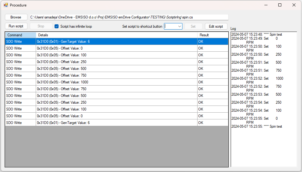
The emDrive Configurator scripting feature lets you create custom C# (.cs) scripts to communicate with CAN Open devices. Scripts can be run in a dedicated Script Window within the application. You can perform actions such as reading and writing device parameters (SDO operations), sending direct commands, managing device states via NMT commands, and even logging or displaying messages. This guide explains the basics—from script file creation to using the scripting API for simple operations.
User Interface Overview
When you open the Script Window (via Device > Script), you will see several controls:
Long-running scripts cannot be used with Shortcuts.
Creating a Script File
All scripts must be written in C#. You can use any text editor or an IDE like Visual Studio Code to create a .cs file. Two common templates are provided:
Basic Template
For quick scripts without long-running loops, use a template similar to this:
using System;
using emDrive_Configurator;  // or "using eDrive_Configurator;" for versions 2.5.4.0 and lower

public class Script
{
    public void Main()
    {
        // Your code here (e.g., SDO read/write, logging, etc.)
        Procedure.Log("Hello from the basic script!");
    }
}
Version 2.5.4.0 and lower use using eDrive_Configurator; instead of using emDrive_Configurator;.
Long-Running Template (Infinite or Looping Scripts)
For scripts that must run continuously (e.g., monitoring sensor values), change the Main method to accept a CancellationToken. This lets the tool cancel your loop when you click Stop.
This feature is available only from version 2.9.0.0 and onwards. Long-running scripts should not be used in versions below 2.9.0.0.
using System;
using System.Threading;
using emDrive_Configurator; // or "using eDrive_Configurator;" for versions 2.5.4.0 and lower

public class Script
{
    public void Main(CancellationToken cancellationToken)
    {
        while (!cancellationToken.IsCancellationRequested)
        {
            // Periodically execute code (e.g., monitor sensor value)
            Procedure.Log("Script running...");
            Procedure.Delay(1000);  // Pause for one second
        }
        Procedure.Log("Script canceled.");
    }
}
Ensure you include using System.Threading; if you are using long-running loops with a cancellation token. (Version 2.9.0.0 and later support this feature.)
Scripting API Methods
The emDrive Configurator exposes several API methods that you can use in your scripts. Below is a detailed summary of the methods available for interacting with your CAN Open device.
Every method needs to be called using the Procedure class as seen in the examples above.
SDO Data Transfers
SDO_Read Methods
These methods read data (Service Data Objects) from the device. They come in several overloads:
bool SDO_Read(int nodeId, uint index, ushort subindex, out object value, out string errMessage);Usage: Reads a parameter from a specified node and object index/subindex. The method converts the device’s hex response into a readable value and returns any error messages if the read fails.
dynamic SDO_Read(int NodeId, uint Index, ushort Subindex);Usage: Returns the read value as a dynamic type after automatically processing the hex data.
bool SDO_Read(int NodeId, uint Index, ushort Subindex, Action<CO_Object, dynamic> Parser);Usage: Reads data and passes the value to a provided callback (Parser) for further processing.
SDO_Write Methods
These methods write a value to a CAN Open object.
bool SDO_Write(int nodeId, uint index, ushort subindex, dynamic value, out string errMessage);Usage: Writes the specified value to a node’s object. It logs the operation and returns a message indicating success or error.
Direct Command Execution
string Direct_Command(string text);Usage: Sends a direct command (as a simple string) to the device and returns the response.
This is recommended only for advanced users who are familiar with the CAN Open protocol on the EMSISO CAN Card
Timing Control
void Delay(int Duration);Usage: A simple wrapper around Thread.Sleep that pauses script execution. The duration is in milliseconds.
Network Management (NMT) Commands
These methods allow you to change the state of CAN Open nodes:
bool NMT_Operational();
bool NMT_Operational(int nodeId);Usage: Switch the device (or a specific node) to Operational Mode.
bool NMT_Preoperational();
bool NMT_Preoperational(int nodeId);Usage: Set the device (or node) into Preoperational Mode.
bool NMT_Stopped();
bool NMT_Stopped(int nodeId);Usage: Stops the device (or node).
bool NMT_Reset();
bool NMT_Reset(int nodeId);
bool NMT_Reset_Communication();
bool NMT_Reset_Communication(int nodeId);Usage: Resets the device or its communication link.
User Interaction and Logging
void ShowMessagebox(string text);Usage: Display a standard message box to the user.
bool ShowDialog(string text);Usage: Open a dialog window that returns a Boolean value (for example, after the user confirms an action).
dynamic InputDialog(string caption);Usage: Shows a prompt for user input and returns the entered text.
Script Examples
Below are two example scripts that illustrate how to use the API methods to interact with CAN Open devices.
Example 1: Basic SDO Read/Write
This example shows how to read a value from a CAN Open object and then write a new temporary value.
using System;
using emDrive_Configurator;

public class Script
{
    public void Main()
    {
        // Define node and object identifiers (using temporary indexes)
        int nodeId = 1;
        uint index = 0x2000;
        ushort subindex = 0x01;

        object readValue;
        string errMessage;

        // Attempt to read the current value from the device
        if (Procedure.SDO_Read(nodeId, index, subindex, out readValue, out errMessage))
        {
            Procedure.Log("SDO Read successful. Value: " + readValue);
        }
        else
        {
            Procedure.Log("SDO Read error: " + errMessage);
        }

        // Set a temporary value and write it to the device
        dynamic tempValue = 123;  // Change 123 to any temporary test value as needed
        if (Procedure.SDO_Write(nodeId, index, subindex, tempValue, out errMessage))
        {
            Procedure.Log("SDO Write successful. New Value: " + tempValue);
        }
        else
        {
            Procedure.Log("SDO Write error: " + errMessage);
        }
    }
}
Example 2: Test with Long-Running Loop
This script continuously reads from the device and exits the loop if a defined break condition is met. It demonstrates the use of a CancellationToken so that the script can be stopped via the UI.
using System;
using System.Threading;
using emDrive_Configurator;

public class Script
{
    // Use this template for scripts with long-running loops.
    public void Main(CancellationToken cancellationToken)
    {
        int nodeId = 1;
        uint index = 0x2000;
        ushort subindex = 0x01;
        int condition = 20;

        while (!cancellationToken.IsCancellationRequested)
        {
            dynamic? value;
            string errMessage;

            if (Procedure.SDO_Read(nodeId, index, subindex, out value, out errMessage))
            {
                Procedure.Log("Current SDO Value: " + value);
            }
            else
            {
                Procedure.Log("Read error: " + errMessage);
            }

            // Check if a break condition is met (example: value equals a specific test value)
            if (value is int && value == condition)
            {
                Procedure.Log("Break condition met. Exiting loop.");
                break;
            }

            // Wait for 1 second before next iteration
            Procedure.Delay(1000);
        }

        Procedure.Log("Script execution completed.");
    }
}
Advanced Scripting
Script-Watch Interoperability
This functionality is only available for emDrive Configurator 2.13.0.0 and later.
These API calls allow the user to add virtual script objects to Watch and write to them, as well as request the last value read for a specific object already in Watch. This can be achieved by using the WatchScriptObject class or the method calls described below.
WatchScriptObject class
The WatchScriptObject class uses the API calls described below but is a more user-friendly approach to this functionality. Unless specified the index and subindex properties will be set automatically. index will always be 0xFFFF and subindex will increment from 0 onwards. If the user wishes to reset the subindex counter they must call the ResetSubIndexCounter method.
public class WatchScriptObject
{
    // Properties
    public string Name { get; }
    public int NodeId { get; } // Default: 0
    public uint Index { get; } // Default: 0xFFFF
    public ushort SubIndex { get; }
    public ushort DataType { get; }

    // Constructors
    public WatchScriptObject(string name, ushort datatype);
    public WatchScriptObject(string name, ushort subindex, ushort datatype);
    public WatchScriptObject(string name, uint index, ushort subindex, ushort datatype);

    // Methods
    public bool TryToAddToWatch();
    public bool TryToAddValueToWatch(dynamic value);
}
The TryToAddToWatch method will attempt to add the virtual object to Watch. See TryAddScriptEntryToWatch method for possible errors.
The TryToAddValueToWatch method will attempt to add the value to the already created virtual object in Watch. See TryAddScriptEntryValue method for possible errors.
TryAddScriptEntryToWatch method
Attempts to create a new script virtual object in Watch with the specified name, nodeId, index, subindex, and datatype. Returns true if successful or false if failed.
public static bool TryAddScriptEntryToWatch(string name, int nodeId, uint index, ushort subindex, ushort datatype)Fail reasons:
- Object with specified
nodeId,indexandsubindexalready exists in Watch.
TryAddScriptEntryValue method
Attempts to write value to the script virtual object in Watch. Returns true if successful or false if failed.
public static bool TryAddScriptEntryValue(int nodeId, uint index, ushort subindex, dynamic value)Fail reasons:
- Object with specified
nodeId,indexandsubindexdoes not exist in Watch. - Failed to convert value to the declared datatype.
TryGetLastWatchValue method
Attempts to get the last read value of the object specified with nodeId, index, subindex and saves it to value. Returns true if successful or false if failed.
public static bool TryGetWatchValue(int nodeId, uint index, ushort subindex, out double value)Fail reasons:
- Object with specified
nodeId,indexandsubindexdoes not exist in Watch. - Failed to convert object value to type
double.
Example file
Example file for Script - Watch Interoperability (also available as download)
/*
  Author:       Amadej Arnus
  Date:         2024-04-23
*/

using System;
using System.Windows.Forms;
using emDrive_Configurator;
using System.Threading;
using Timer = System.Threading.Timer;

using System.Collections.Generic;
using System.Diagnostics;
using System.Drawing;
using System.Globalization;
using System.IO;
using System.IO.Ports;
using System.Linq;
using System.Management;
using System.Text;
using System.Text.RegularExpressions;

public class Script
{
    // Prepare error string
    string err = string.Empty;

    // Create object that we will attempt to read from watch
    CO_Object HwMonitorUdc = new CO_Object(0x3071, 0x00);

    public void Main(CancellationToken cancellationToken)
    {
        // This will run the example for the WatchScriptObject
        ObjectBasedVersion(cancellationToken);

        // This will run the example for the API calls
        //ObjectBasedVersion(cancellationToken);
    }

    private void ObjectBasedVersion(CancellationToken cancellationToken)
    {
        // Create new objects for watch-script interoperability
        Procedure.WatchScriptObject intObject = new Procedure.WatchScriptObject("ScriptObject_Int32", 0x0004);
        Procedure.WatchScriptObject floatObject = new Procedure.WatchScriptObject("ScriptObject_Real32", 0x0008);

        // Add int object to watch
        if (intObject.TryToAddToWatch())
        {
            LogResult("ScriptObject_Int32 added to watch");
        }
        else
        {
            LogResult("ScriptObject_Int32 not added to watch");
        }

        // Add float object to watch
        if (floatObject.TryToAddToWatch())
        {
            LogResult("ScriptObject_Real32 added to watch");
        }
        else
        {
            LogResult("ScriptObject_Real32 not added to watch");
        }

        int i = 0;

        // Do the loop until cancellationToken is requested
        while (!cancellationToken.IsCancellationRequested)
        {
            double hwMonitorValue = 0;

            // Read last value of HwMonitorUdc object
            if (HwMonitorUdc.TryGetWatchValue(1, out hwMonitorValue))
            {
                i++;

                // Set new value to int and float objects
                if (!intObject.TryToAddValueToWatch(i))
                {
                    LogResult("Failed to write value to ScriptObject_Int32");
                }

                if (!floatObject.TryToAddValueToWatch(hwMonitorValue * 1.5))
                {
                    LogResult("Failed to write value to ScriptObject_Real32");
                }
            }
            // If not successful, log the error
            else
            {
                LogResult("Failed to get HwMonitorUdc value");
            }

            Procedure.Delay(200);
        }
    }

    private void ApiBasedVersion(CancellationToken cancellationToken)
    {
        // Add int object to watch
        if (TryAddScriptEntryToWatch("ScriptObject_Int32", 1, 0xFFFF, 0x01, datatype: 0x0004))
        {
            LogResult("ScriptObject_Int32 added to watch");
        }
        else
        {
            LogResult("ScriptObject_Int32 not added to watch");
        }

        // Add float object to watch
        if (TryAddScriptEntryToWatch("ScriptObject_Real32", 1, 0xFFFF, 0x02, datatype: 0x0008))
        {
            LogResult("ScriptObject_Real32 added to watch");
        }
        else
        {
            LogResult("ScriptObject_Real32 not added to watch");
        }

        int i = 0;

        // Do the loop until cancellationToken is requested
        while (!cancellationToken.IsCancellationRequested)
        {
            double hwMinutorValue = 0;

            // Read last value of HwMonitorUdc object
            if (TryGetWatchValue(1, 0x3071, 0x00, out hwMinutorValue))
            {
                i++;

                // Set new value to int and float objects
                if (!TryAddScriptEntryValue(1, 0xFFFF, 0x01, i))
                {
                    LogResult("Failed to write value to ScriptObject_Int32");
                }

                if (!TryAddScriptEntryValue(1, 0xFFFF, 0x02, hwMinutorValue * 1.5))
                {
                    LogResult("Failed to write value to ScriptObject_Real32");
                }
            }
            // If not successful, log the error
            else
            {
                LogResult("Failed to get HwMonitorUdc value");
            }

            Procedure.Delay(200);
        }
    }

    // The following methods are just wrappers to shorten the method calls
    bool TryAddScriptEntryToWatch(string name, int nodeId, uint index, ushort subindex, ushort datatype)
    {
        return Procedure.TryAddScriptEntryToWatch(name, nodeId, index, subindex, datatype);
    }
    bool TryAddScriptEntryValue(int nodeId, uint index, ushort subindex, dynamic value)
    {
        return Procedure.TryAddScriptEntryValue(nodeId, index, subindex, value);
    }
    bool TryGetWatchValue(int nodeId, uint index, ushort subindex, out double value)
    {
        return Procedure.TryGetWatchValue(nodeId, index, subindex, out value);
    }

    void LogResult(string LogString)
    {
        LogString = DateTime.Now.ToString("yyyy-MM-dd HH:mm:ss") + ": " + LogString;
        Procedure.Log(LogString);
    }
}

// CO_Object for readability
class CO_Object
{
    public uint index;
    public ushort subindex;
    public dynamic value;

    public CO_Object(uint index, ushort subindex)
    {
        this.index = index;
        this.subindex = subindex;
    }

    public bool TryGetWatchValue(int nodeId, out double value)
    {
        return Procedure.TryGetWatchValue(nodeId, index, subindex, out value);
    }
}
Script Features
Script features are extensions to the scripting functionality.
In order to use script features, the user must add
using emDrive_Configurator.Scripts.Features;Modbus TCP
This functionality is only available for emDrive Configurator 2.13.1.0 and later.

ModbusTCP currently supports connection with Modbus Servers (Client Mode) through TCP. In order to connect to the device, you need to provide the IP Address, Port and Modbus Server ID (Bus Address).
In the following Example, the IP is 127.0.0.1, the Port is 502 and the Modbus Server ID is 1:
ModbusTCP ModbusDevice1 = new ModbusTCP("127.0.0.1", 502, 1);Alternatively, the device endianness can also be specified in the connection constructor:
ModbusTCP ModbusLocalhost = new ModbusTCP("127.0.0.1", 502, 1, ModbusEndianness.LittleEndian);Default Endianness is set to Big Endian.
Currently Read and Write Holding registers operation is supported using generic functions:
short i16_var = 0;

// Read Holding Register at Address 100
if(ModbusLocalhost.ReadHoldingRegister<short>(100, out i16_var) == true)
{
  // Read Successful
}
else
{
  // Read Failed
}

// Write Holding Register at Address 100
ModbusLocalhost.WriteHoldingRegister(100, i16_var);
Supported data types:
- short
- ushort
- int
- uint
- float
Useful Learning Resources
If you’re new to C# or need additional reading to get familiar with the language and its concepts, check out these established sources:
-
Microsoft C# Documentation:
Comprehensive reference and tutorials on the C# language.
https://docs.microsoft.com/en-us/dotnet/csharp/ -
C# Language Reference:
Detailed descriptions of language syntax, keywords, and code examples.
https://docs.microsoft.com/en-us/dotnet/csharp/language-reference/ -
.NET Tutorials:
Learn the fundamentals of C#, .NET Framework, and best practices.
https://docs.microsoft.com/en-us/dotnet/core/tutorials/
Additional Tips and Conclusion
Version Considerations
For scripts with long-running loops, ensure you are using version 2.9.0.0 or later, which supports using a CancellationToken.
Earlier versions (e.g., 2.5.4.0 and lower) require a different namespace (using eDrive_Configurator;).
Script Debugging
Utilize the Log output function (Procedure.Log) to print messages and debug your script during execution.
Integration with Watch
Use the WatchScriptObject class to monitor variable values during script execution. This can help you verify that the SDO read/write operations are working as expected.
By following this guide, even users with minimal technical expertise will be able to write, run, and troubleshoot simple C# scripts to interact with CAN Open devices via the emDrive Configurator. Experiment with the examples provided and consult the useful links if you need further insight into C# programming.
Happy scripting!
Parameters
Object's Attributes
Each CANopen Object in emDrive inverter has several attributes. Following attributes are related to changing, storing and loading values of objects.
| Attribute | Description |
| Access Type | Defines if the object is readable and/or writable |
| Default Value | Default value is value that the object is set to when setting parameters to factory/manufacturer defaults |
| Read Level | Access level that is required for reading value of object |
| Write Level | Access level that is required for writing value to object |
| Persistent | Defines if the value of object is saved in permanent storage (keeps value after reboot or power cycle) |
Object which have Persistent attribute set to "1" are stored in permanent memory and are therefore called "Parameters".
Objects attributes are visible in EDS or DCF files.
See Access Levels for more information about access to objects.
Parameters Sections
There are several different "sections" where parameters can be saved or restored from.
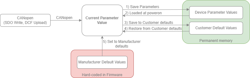
Current Parameter Values
Current value of parameter that is in use. This values are used by applications, firmware and can be access and changed via CANopen or custom CAN messages, depending on inverter.
Manufacturer Default Values
This values are hardcoded into firmware and are used to restore the device to factory default configuration. See section "Restore Manufacturer defaults - "Factory Reset" (5)"
Customer Default Values
Customer defaults is special section that can be used by Emsiso customer during their configuration or alternatively can be loaded at production. Customer has than the ability to reset configuration to their desired defaults i.e. "Customer defaults" without completely resetting parameters to factory defaults.
See sections "Saving to Customer defaults (3)" and "Restore Customer defaults (4)" on how to store values and restore values from this section.
Device Parameter Values
Parameter values stored into permanent memory that are loaded at every power up. See section "Saving Device parameters (1)" on how to save current configuration.
There is also addition section "Calibration parameter" which is used for calibration in production. Customer does not have access to it. Objects that are stored in that section will be loaded from that section at powerup.
Saving and Restoring Parameters
Saving Device parameters (1)
Saving parameters is done by SDO write to CANopen object with index 0x1010 - "Store_Parameters_Field". Writing value 0x73617665 (ASCII "save") or byte swapped value 0x65766173 to any of sub indexes 0x01-0x04. Return status of SDO write will indicate success of failure.
Saving can also be done within emDrive Configurator by selecting "Device" -> "Save parameters" or by using shortcut "CTRL + S".
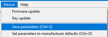 Saving parameters in emDrive Configurator
Saving to Customer defaults (3)
Saving parameters to "Customer Defaults" section is done by SDO write to CANopen object with index 0x1010 - "Store_Parameters_Field". Writing value 0x73617665 (ASCII "save") or byte swapped value 0x65766173 to sub index 0x05 "Save_Customer_Defined_Parameters. Return status of SDO write will indicate success of failure.
Saving can also be done within emDrive Configurator by selecting "Device" -> "Save to customer parameters" or by using shortcut "CTRL + SHIFT + S".
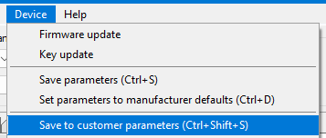 Saving parameters to Customer defaults in emDrive Configurator
Saving to Customer defaults is only possible with Access Level 2 (Customer) or above.
Restore Manufacturer defaults - "Factory Reset" (5)
Restoring parameter values to manufacturer defaults is done by SDO write to CANopen object with index 0x1011 - "Restore_Default_Parameters". Writing value 0x6C6F6164 (ASCII "load") or byte swapped value 0x64616F6C to any of sub index 0x01-0x04. Return status of SDO write will indicate success of failure.
Restoring can also be done within emDrive Configurator by selecting "Device" -> "Set parameters to manufacturer defaults" or by using shortcut "CTRL + D".
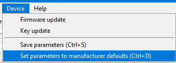
Setting parameters to manufacturer defaults in emDrive Configurator
Restoring from manufacturer defaults is only possible with Access Level 2 (Customer) or above.
Restore Customer defaults (4)
Restoring parameter values to Customer defaults is done by SDO write to CANopen object with index 0x1011 - "Restore_Default_Parameters". Writing value 0x6C6F6164 (ASCII "load") or byte swapped value 0x64616F6C to sub index 0x05 "Restore_Cusstomer_Define_Default_Parameters. Return status of SDO write will indicate success of failure.
Restoring to Customer defaults can also be done within emDrive Configurator by selecting "Device" -> "Set parameters to customer defaults" or by using shortcut "CTRL + SHIFT + D".
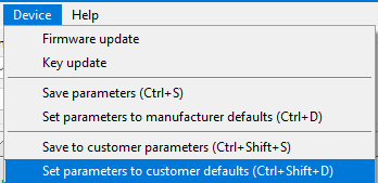 Restoring parameters from Customer defaults in emDrive Configurator
After each operation device shall be reset to apply new values.
Access Level
Access Level functionality is different depending on the emDRIVE firmware version.
Up to V1.14.x
Access Level is emDrive functionality that is used to limit read and write permissions for objects depending on user granted access.
Access Level functionality is available from firmware V1.11.0 and newer.
Each Parameter has attribute (Object's Attributes) for Read and Write access level. To be able to read or write to object Inverter must be unlocked to required level.
Access Levels
| Level | Name | Description |
| 1 | End User | Object is available to End User even when inverter is locked with "Customer Key" |
| 2 | Customer | Object is available by default. Can be locked with "Customer Key" |
| 3 | Production | Object is available only in production to write production related and calibration objects (only Emsiso) |
| 4 | Development | Object is available only during development (only Emsiso) |
Devices shipped from manufacturer are unlocked to "Customer" level. Customer has the option to lock the device and prevent additional changing of object values from 3rd parties.
Access Level CANopen Objects
Objects at index 0x2010 are used for Access Level functionality
| Sub - index | Name | Description |
| 0x01 | Access_Level__Current | Shows current access level that inverter is set to, objects with equal or lower access level can be accessed. |
| 0x02 | Access_Level_Key_input | Write your key to unlock the device, depending on the key, specific level will be unlocked. |
| 0x03 | Access_Level_Customer_Key | Writing value to this object will lock the device to "End User" (after reset). The same key must be used to unlock the device to "Customer" level. Remove locking by writing value "0". |
Locking emDrive
Lock the emDrive inverter is intended to be used by Customer to prevent End User to make any changes of configuration. Objects with End User access level are mostly Read Only objects or only Read Access Level is set to End User.
To lock the emDrive follow the steps
- Chose the secret key that will be used to lock and unlock the inverter. Value can be from 1 - 4294967295 (32-bit unsigned integer).
- Write chosen key to object "Access_Level_Customer_Key"
- Save Device Parameters
- Reset the device
- After power up, device will have Current Access Level at 1 - End User. Check by reading object "Access_Level__Current"
Unlocking emDrive
If the emDrive is locked with Customer key and we want to change parameters that require Access Level 2, we have to unlock the emDrive after each power on. To verify that emDrive is locked, read object "Access_Level__Current" which should read "1".
To unlock the emDrive follow the steps
- Write correct Customer Key to object "Access_Level_Key_input".
- Read object "Access_Level__Current" which should change to "2" if the key was correct.
At this point Customer Level object can be read/written. But if the emDrive is reset, it will return to locked End User Access Level. To permanently unlock the emDrive and remove the key follow additional steps are needed.
- Write correct Customer Key to object "Access_Level_Key_input".
- Read object "Access_Level__Current" which should change to "2" if the key was correct.
- Write value "0" to "Access_Level_Customer_Key" to remove the key.
- Save Device Parameters
- Reset the device
- After power up, device will have Current Access Level at 2 - Customer. Check by reading object "Access_Level__Current"
V1.15.0+
Access Level is a feature of emDrive that controls read and write permissions for various objects based on the user’s granted access.
Access Level functionality is available from firmware V1.11.0 and newer.
Each parameter in emDrive has attributes (Object's Attributes) that define the required Read and Write Access Level. To interact with these parameters, the inverter must be unlocked to the corresponding access level. Higher access levels grant access to a greater number of objects.
Access Levels
| Level | Name | Description |
| 0 | End User | Available to the End User, even when the inverter is locked with the "Service Key". |
| 1 | Service | Available to Service personnel. Can be locked using the "Service Key". |
| 2 | Admin | Available by default. Can be locked using the "Admin Key". |
| 3 | Production | Accessible only in production for writing production-related and calibration objects (Emsiso). |
| 4 | Development | Accessible only during development (Emsiso). |
Devices shipped from the manufacturer are unlocked to the "Admin" level. The customer has the option to lock the device, preventing third parties from changing object values.
Access Level CANopen Objects
The following objects at index 0x2010 are used to control Access Level functionality:
| Sub - index | Name | Description |
| 0x01 | Access_Level__Current | Displays the current access level of the inverter. Objects with equal or lower levels can be accessed. |
| 0x02 | Access_Level__Key_input | Enter a key to unlock the device. The entered key will unlock a specific level. |
| 0x03 |
Access_Level__Admin_Key
|
Write a value to lock the device to "Admin" level after reset. Use the same key to unlock. Write "0" to remove locking. |
| 0x04 |
Access_Level__Service_Key
|
Write a value to lock the device to "Service" level after reset. Use the same key to unlock. Write "0" to remove locking. |
Locking emDrive
Locking the emDrive inverter is typically performed by the Admin or Service personnel to prevent the End User from making configuration changes. Objects accessible to the End User are usually read-only or have read-only permissions set.
To lock the emDrive follow the steps
- Choose a secret key (an integer between 1 and 4,294,967,295).
- Write the selected key to either the "Access_Level__Service_Key" or "Access_Level__Admin_Key" depending on the desired lock level.
- Save the device parameters.
- Reset the device
- After powering up, the device will be locked one level below the set key. Verify this by reading the "Access_Level__Current" object.
Unlocking emDrive
To modify parameters that require higher access levels (such as Admin or Service), the emDrive must be unlocked after every power cycle. To confirm that the emDrive is locked, check the "Access_Level__Current" object, which should display the correct locked level.
To unlock the emDrive:
- Write the correct key to the "Access_Level__Key_input" object.
- Read the "Access_Level__Current" object to verify the change to the corresponding access level.
Once unlocked, objects at the unlocked level can be accessed. However, if the emDrive is reset, it will revert to the locked state. To permanently unlock the emDrive, follow these additional steps:
- Write the correct key to the "Access_Level__Key_input" object.
- Verify that the access level has changed by reading "Access_Level__Current".
- Write the value "0" to "Access_Level__Admin_Key" or "Access_Level__Service_Key" to remove the respective key.
- Save the device parameters.
- Reset the device.
After the reset, the device will no longer require the key to access the previous locked level. You can verify this by checking the "Access_Level__Current" object.
Lua Manual
Disclaimer
The EMSISO d.o.o. scripting functionality, based on the Lua programming language, is provided to enable flexibility and customization for motor control applications. However, EMSISO d.o.o. assumes no responsibility or liability for any damages, malfunctions, injuries, or losses resulting from the use of scripts provided by EMSISO d.o.o. or scripts created, modified, or executed by users.
Users are fully responsible for testing and verifying all scripts in a controlled and safe environment before deployment. Any script used in conjunction with EMSISO d.o.o. products is done at the user’s own risk.
By using the scripting feature, you acknowledge and agree to release EMSISO d.o.o. from all claims, demands, or liability for any incidents that may arise from its use.
1. General
1.1 Purpose
- This manual helps you create and run Lua scripts on emDrive.
- It also informs you about any warnings and known issues.
1.2 Scope
- The manual covers Lua scripting features, including how to:
- Download scripts
- Control scripts
- Debug scripts
- Use functions provided by the emDrive library
- It also lists known issues and limitations of the scripting functionality.
1.3 Important Note
- This manual assumes you already know Lua and emDrive Configurator software.
- It is valid for Lua version 5.4. For more details on Lua, visit:
2. emDrive library
2.1 General
The emDrive library is used instead of the standard Lua libraries. This library includes some functions that are identical to those in the standard Lua library, some that have been modified, and others that are unique to emDrive.
Do not overwrite the emDrive library functions and variables.
The emDrive library is organized into different sets, each focused on a specific group of functionalities. This section will describe these sets and their functions and variables in detail.
Here is an example of how to use a library function. This example will show a legend that explains how to read the prototypes of library functions. Words in blue represent variable types, such as arguments or return values. These types follow standard Lua conventions, with the addition of the "integer" type, which represents whole numbers.
When your script calls a function from the emDrive library, the arguments you provide must match the prototype exactly, including the type and, for tables, their structure. If they do not, an error will occur.
number | nil ret1, boolean ret2 = Namespace.FunctionName({integer arg1Field1, string arg1Field2} arg1,
{integer, integer, integer [5:5-11], integer [13]} arg2, [, string arg3], arg4…)
This is an example of a function named Namespace.FunctionName. It takes in: 2 fixed arguments, 1 optional
argument and a variable number of arguments. It also returns 2 values where the first can also be nil.
|
|
Name |
Description |
|
Arguments |
arg1 |
Table with two named fields arg1Field1 of type integer and arg1Field2 of type string. |
|
arg2 |
Table with unnamed fields with all integer types at index 1, 2, 5 with size 1 to 7 and 13. |
|
|
arg3 |
Optional string argument. |
|
|
arg4 |
Variable number of arguments of any type. |
|
|
Returns |
ret1 |
First returned value which can be either a number type or nil. |
|
ret2 |
Second returned value which is of boolean type. |
Functions can be called with more arguments then expected in which case excess arguments are ignored.
The emDrive library can raise errors in addition to those raised by the Lua kernel, such as accessing nil values. These library errors usually occur when the type or value of an argument does not match what is expected.
For each function in the emDrive library, the possible errors (exceptions) and the conditions that cause them will be listed.
2.2 Functions
2.2.1 Base
This library provides base script functionality that is not specific to any part of the emDrive hardware (HW) or firmware (FW).
Error(string message [, integer level])
The Error function raises an error with a custom message and specifies the level of the error position. It is useful for throwing exceptions, such as for debugging purposes. This function is equivalent to the standard error() function in Lua and never returns.
|
|
Name |
Description |
|
Arguments |
message |
Error message shown. |
|
level |
Specify how to get the error position: · 0, error position is not added, · 1 (default), the error position is where the error() function was called, · 2 points the error to where the function that called error() was called, · and so on… |
2.2.2 I/O
This library works with two main objects: Lua__IO_Input and Lua__IO_Output. These objects facilitate communication between the script and the external world, such as displaying messages or providing debugging arguments to the script.
- Access: These objects can be accessed via the CANopen index
0x2040. - Purpose:
Lua__IO_Input: Used to input data into the script.Lua__IO_Output: Used to output data from the script.
By using these objects, the script can efficiently exchange information with external systems.
___________________________________________________________________________________________________________________________________________
number | string | nil value = IO.Read([option…])
You can read values from the input object using specified options.
Options:
- When the 'n' option is selected, if the value cannot be converted to a number,
nilis returned. - By passing an integer, you can read that many number of characters.
This function is equivalent to the standard io.read() function in Lua.
|
|
Name |
Description |
|
Arguments |
option |
How to interpret the input string: · ‘n’ as a number, · ‘l’ (default) as one line string without newline, · ‘L’ as one line string with newline if exists, · ‘a’ as string of all text, · 0, 1, 2, … as number of characters. |
|
Returns |
value |
Interpreted input. |
|
Exception |
|
option is not an integer nor a string. |
|
option is a string longer than 1 character. |
|
option is a string but not one of the valid values. |
___________________________________________________________________________________________________________________________________________
IO.Write(string text…)
You can write text to the output object using this function.
- Behavior:
- If the text is short enough, it is appended to the existing output string.
- If the text is too long, the existing output string is overwritten.
This function is equivalent to the standard io.write() function in Lua.
|
|
Name |
Description |
|
Arguments |
text |
Text to write to output object. |
|
Exception |
|
text is not a string. |
___________________________________________________________________________________________________________________________________________
IO.Print(object…)
This function converts an object to a string and then writes the result to the output object.
This function is equivalent to the standard print() function in Lua.
|
|
Name |
Description |
|
Arguments |
object |
Objects to convert to string and write to output object. |
2.2.3 Time
This library provides functions for time keeping and inserting delays in your scripts.
___________________________________________________________________________________________________________________________________________
integer time = Time.GetMs()
This function retrieves the current time in milliseconds since the device was powered on. The maximum value is limited to 2³² – 1.
|
|
Name |
Description |
|
Returns |
time |
Elapsed milliseconds since power on. |
___________________________________________________________________________________________________________________________________________
Time.WaitMs(integer time)
This function halts the script execution for a specified amount of time using this function.
|
|
Name |
Description |
|
Returns |
time |
Milliseconds to wait. |
|
Exception |
|
time is negative or 0. |
___________________________________________________________________________________________________________________________________________
integer newStartTime = Time.WaitMsUntil(integer startTime, integer waitTime)
This function halts script execution for specified time from the provided starting time. This function can be used to implement periodic execution independent of logic execution duration.
|
|
Name |
Description |
|
Arguments |
startTime |
Time (milliseconds) from which waiting time is measured. |
|
waitTime |
Milliseconds to wait. |
|
|
Returns |
newStartTime |
Time (milliseconds) at which script was halted. |
|
Exception |
|
startTime is negative or 0. |
|
waitTime is negative or 0. |
2.2.3 CAN
This library is used to establish communication and transfer data over CAN. It provides functionality to send and receive CAN messages.
Note: This library does not support CAN FD (Flexible Data-rate).
___________________________________________________________________________________________________________________________________________
This library supports two modes of operation for CAN communication. The mode is selected during the initialization of CAN.
|
Mode |
Description |
|
CAN_RX_TX |
CAN shall be used to send and receive messages (user is required to implement CAN.Received(message) function). |
|
CAN_TX_ONLY |
CAN shall be used only to send messages. |
___________________________________________________________________________________________________________________________________________
CAN.Initialize(mode, boolean useExtendedFrame [, integer rxID, integer rxIDMask])
To use CAN communication, initialize CAN with this function. It can be called multiple times with different arguments, but only the last configuration will be used.
- rxIDMask Argument: Required only when the operating mode is set to
CAN_RX_TX.
|
|
Name |
Description |
|
Arguments |
mode |
CAN mode of operation (see Table 12). |
|
useExtendedFrame |
Will extended frames be transferred? |
|
|
rxID |
Frame ID to receive. |
|
|
rxIDMask |
Receive filter ID mask. |
|
Exception |
|
mode is not one of the valid values. |
|
useExtendedFrame is not boolean. |
|
rxID is not an integer. |
|
mode is set to CAN_RX_TX and rxIDMask is not an integer. |
|
CAN initialization failed (should never happen). |
___________________________________________________________________________________________________________________________________________
CAN.Send(integer id, {integer [1:1-8]} data)
Use this function to send a CAN frame with a specified ID and data.
|
|
Name |
Description |
|
Arguments |
id |
Sent frame ID. |
|
data |
1 to 8 bytes of data. |
|
Exception |
|
id is not an integer. |
|
data is not a table. |
|
Length of data is more than 8. |
|
Value of data is not an integer. |
|
Value of data is more than 0xFF. |
|
CAN send failed (should never happen). |
___________________________________________________________________________________________________________________________________________
CAN.Received({integer ID, integer Length, integer Data[1:1-8]} message)
This function is called whenever a CAN message is received.
- User Implementation Required: You must implement this function if CAN is initialized in
CAN_RX_TXoperating mode.
|
|
Name |
Description |
|
Arguments |
message |
Received message. |
2.2.4 CANopen
This library is used to interact with the CANopen protocol stack.
- CANopen Object Representation: Internally, a CANopen object is represented as a table with two values:
indexandsubindex.
___________________________________________________________________________________________________________________________________________
The CANopen stack includes a network management state machine that defines the communication behavior of a CANopen device. While there are multiple possible states, only a few are regularly used and available to the user.
|
NMT state |
Description |
|
CO_UNKNOWN |
NMT in unknown state (unreachable). This state cannot be set by user. |
|
CO_OPERATIONAL |
Device can use all supported communication objects. This state can be set by user. |
|
CO_STOPPED |
Device operation is stopped. This state cannot be set by user. |
|
CO_PREOPERATIONAL |
First state after initialization indicating that device is ready to work. Limited message transfer support. This state can be set by user. |
|
CO_RESET_NODE |
Application reset. Application objects set to their power-on or default values. This state cannot be set by user. |
|
CO_RESET_COMM |
Communication reset. Communication objects are set to their power-on or default values. This state cannot be set by user. |
___________________________________________________________________________________________________________________________________________
state = CANopen.GetNMTState()
Use this function to retrieve the currently set Network Management (NMT) state of the CANopen device.
|
|
Name |
Description |
|
Arguments |
state |
Currently set NMT state (see Table 18). |
___________________________________________________________________________________________________________________________________________
CANopen.SetNMTState(state)
Use this function to request the CANopen stack to change the Network Management (NMT) state of the device.
|
|
Name |
Description |
|
Arguments |
state |
Next NMT state (see Table 18). |
|
Exception |
|
state is not one of the valid values. |
___________________________________________________________________________________________________________________________________________
number value = CANopen.GetObjectValue({integer, integer} object)
Use this function to retrieve the value of a specified object.
|
|
Name |
Description |
|
Arguments |
object |
CANopen object. |
|
Returns |
value |
Object value. |
|
Exception |
|
object is not a table. |
|
Length of object is not 2. |
|
Value at first index of object is not an integer. |
|
Value at second index of object is not an integer. |
|
Invalid object index and/or subindex. |
___________________________________________________________________________________________________________________________________________
CANopen.SetObjectValue({integer, integer} object, number value)
Use this function to set the value of a specified object.
|
|
Name |
Description |
|
Arguments |
object |
CANopen object. |
|
value |
Object value. |
|
Exception |
|
object is not a table. |
|
Length of object is not 2. |
|
Value at first index of object is not an integer. |
|
Value at second index of object is not an integer. |
|
Invalid object index and/or subindex. |
|
Value is not a number |
2.2.5 Motor
This library is used to operate the motor. You can set operating parameters and retrieve the motor's current state and status.
___________________________________________________________________________________________________________________________________________
The motor can be controlled in three distinct modes. Depending on the chosen mode, the related reference will be used by the motor control algorithm.
|
Motor control mode |
Description |
|
TORQUE_MODE |
Motor is torque controlled. Set requested torque with Motor.SetReferenceTorque(). |
|
VELOCITY_MODE |
Motor is velocity controlled. Set requested velocity with Motor.SetReferenceVelocity(). |
|
POSITION_MODE |
Motor is position controlled. Set requested torque with Motor.SetReferencePosition(). |
___________________________________________________________________________________________________________________________________________
Motor control operates with a state machine that can be in one of multiple states. This state machine is responsible for top-level motor control functions such as initialization, execution, calibration, and error handling.
- State Execution: Some states are executed before the script runs and will not be visible to the user.
|
Motor control state |
Description |
|
MOTOR_UNDEFINED |
Motor control in undefined state (internal error). |
|
MOTOR_INITIALIZATION |
Motor control is initializing. |
|
MOTOR_SELF_TEST |
Motor control is performing start-up self-tests. |
|
MOTOR_OFF |
Motor control is initialized and disabled. Controlling the motor is not possible. Reference values have no effect. |
|
MOTOR_ON |
Motor control is initialized and enabled. Motor is controlled according to mode and reference value such that the operating conditions are always within defined limits. |
|
MOTOR_ERROR |
Motor control detected an error and was disabled. This state can be entered in multiple ways: limits overreached, failed calibration and other. |
|
MOTOR_CALIBRATION |
Motor control is being calibrated. In this state characteristics of the motor and angle sensor are being measured. |
___________________________________________________________________________________________________________________________________________
Motor.Enable()
Enable motor control to have the motor operate according to the set mode and the corresponding reference value.
___________________________________________________________________________________________________________________________________________
Motor.Disable()
Disable motor control to stop the motor.
___________________________________________________________________________________________________________________________________________
Motor.Recover()
Use this function to attempt recovery from a motor control error.
Note: This function is only applicable when the motor control is in an error state.
___________________________________________________________________________________________________________________________________________
Motor.SetControlMode(mode)
Use this function to set the motor control mode.
|
|
Name |
Description |
|
Arguments |
mode |
Motor control mode (see Table 26). |
|
Exception |
|
mode is not one of the valid values. |
___________________________________________________________________________________________________________________________________________
state = Motor.GetState()
Retrieve the current state of the motor control.
|
|
Name |
Description |
|
Returns |
state |
Motor control state (see Table 27). |
___________________________________________________________________________________________________________________________________________
integer warnings = Motor.GetWarnings()
Retrieve the currently active motor control warnings.
|
|
Name |
Description |
|
Returns |
warnings |
Active warnings. Refer to emDrive manual or related CANopen object for value meaning. |
___________________________________________________________________________________________________________________________________________
integer protectionsLow = Motor.GetProtectionsLow()
Retrieve the currently active motor control protections (first 32 bits).
|
|
Name |
Description |
|
Returns |
protectionsLow |
Active protections (first 32bits). Refer to emDrive manual or related CANopen object for value meaning. |
___________________________________________________________________________________________________________________________________________
integer protectionsHigh = Motor.GetProtectionsHigh()
Retrieve the currently active motor control protections (last 32 bits).
|
|
Name |
Description |
|
Returns |
protectionsHigh |
Active protections (second 32 bits - currently empty meant for future FW releases). Refer to emDrive manual or related CANopen object for value meaning. |
___________________________________________________________________________________________________________________________________________
number velocity = Motor.GetReferenceVelocity()
Retrieve the currently set reference velocity.
|
|
Name |
Description |
|
Returns |
velocity |
Velocity [RPM]. |
___________________________________________________________________________________________________________________________________________
Motor.SetReferenceVelocity(number velocity)
Set the reference velocity.
|
|
Name |
Description |
|
Arguments |
velocity |
Velocity [RPM]. |
|
Exception |
|
velocity is not a number. |
___________________________________________________________________________________________________________________________________________
number torque = Motor.GetReferenceTorque()
Retrieve the currently set reference torque.
|
|
Name |
Description |
|
Returns |
torque |
Torque [Nm]. |
___________________________________________________________________________________________________________________________________________
Motor.SetReferenceTorque(number torque)
Set the reference torque.
|
|
Name |
Description |
|
Arguments |
torque |
Torque [Nm]. |
|
Exception |
|
torque is not a number. |
___________________________________________________________________________________________________________________________________________
number position = Motor.GetReferencePosition()
Retrieve the currently set reference position.
|
|
Name |
Description |
|
Returns |
position |
Position [°]. |
___________________________________________________________________________________________________________________________________________
Motor.SetReferencePosition(number position)
Set the reference position.
|
|
Name |
Description |
|
Arguments |
position |
Position [°C]. |
|
Exception |
|
position is not a number. |
___________________________________________________________________________________________________________________________________________
number velocity = Motor.GetVelocity()
Retrieve the current motor velocity.
|
|
Name |
Description |
|
Returns |
velocity |
Velocity [RPM]. |
___________________________________________________________________________________________________________________________________________
number torque = Motor.GetTorque()
Retrieve the current motor torque.
|
|
Name |
Description |
|
Returns |
torque |
Torque [Nm]. |
___________________________________________________________________________________________________________________________________________
number position = Motor.GetPosition()
Retrieve the current motor position.
|
|
Name |
Description |
|
Returns |
position |
Position [°C]. |
___________________________________________________________________________________________________________________________________________
Motor.TriggerProtection(number ErrorCode, string ErrorMessage)
Raise inverter protection from Lua
|
|
Name |
Description |
|
Arguments |
ErrorCode |
Create custom value for error code |
|
|
ErrorMessage |
Custom error description |
|
Exception |
|
ErrorCode is not a number |
2.2.6 Digital
This library is used to manipulate digital I/Os (ports). It enables writing to and reading from digital ports.
___________________________________________________________________________________________________________________________________________
Every emDrive contains a set of digital ports that can be freely used by the user application. Some of these ports are writable, while others are read-only. Note that some ports might not be available on all emDrives. To see which ports are available, refer to the manual or the EDS of your emDrive
|
Digital port |
Description |
|
LOW_SIDE_1 |
Low-side switch 1. |
|
LOW_SIDE_2 |
Low-side switch 2. |
|
LOW_SIDE_3 |
Low-side switch 3. |
|
LOW_SIDE_4 |
Low-side switch 4. |
|
HIGH_SIDE_1 |
High-side switch 1. |
|
DIGITAL_IN_1 |
Digital input 1. This port is read-only. |
|
DIGITAL_IN_2 |
Digital input 2. This port is read-only. |
|
DIGITAL_IN_3 |
Digital input 3. This port is read-only. |
|
DIGITAL_IN_4 |
Digital input 4. This port is read-only. |
|
DIGITAL_IN_5 |
Digital input 5. This port is read-only. |
|
DIGITAL_IN_6 |
Digital input 6. This port is read-only. |
|
DIGITAL_IN_7 |
Digital input 7. This port is read-only. |
___________________________________________________________________________________________________________________________________________
number state = Digital.Get(port)
Retrieve the digital state of the port.
|
|
Name |
Description |
|
Arguments |
port |
Digital port (see Table 44). |
|
Returns |
state |
Value of 0 – 1 representing signal’s duty cycle. |
|
Exception |
|
port is not one of the valid values. |
___________________________________________________________________________________________________________________________________________
Digital.Set(port, number state)
Set the digital state of the port.
|
|
Name |
Description |
|
Arguments |
port |
Digital port (see Table 44). |
|
state |
Value of 0 – 1 representing signal’s duty cycle. |
|
Exception |
|
port is not one of the valid values. |
|
state is not a number between 0 and 1. |
___________________________________________________________________________________________________________________________________________
2.2.7 Analog
This library is used to retrieve values from analog inputs (ports).
___________________________________________________________________________________________________________________________________________
Every emDrive contains a set of analog ports that can be freely used by the user application. All of these ports are read-only. Note that some ports might not be available on all emDrives. To see which ports are available, refer to the manual or the EDS of your emDrive.
|
Analog port |
Description |
|
ANALOG_IN_1 |
Analog input 1. |
|
ANALOG_IN_2 |
Analog input 2. |
|
ANALOG_IN_3 |
Analog input 3. |
|
ANALOG_IN_4 |
Analog input 4. |
|
LOW_SIDE_1_VOLTAGE |
Low-side switch 1 voltage measurement. |
|
LOW_SIDE_1_CURRENT |
Low-side switch 1 current measurement. |
|
LOW_SIDE_2_VOLTAGE |
Low-side switch 2 voltage measurement. |
|
LOW_SIDE_3_VOLTAGE |
Low-side switch 3 voltage measurement. |
|
LOW_SIDE_4_VOLTAGE |
Low-side switch 4 voltage measurement. |
|
HIGH_SIDE_1_VOLTAGE |
High-side switch 1 voltage measurement. |
|
DIGITAL_IN_1 |
Digital input 1. |
|
DIGITAL_IN_2 |
Digital input 2. |
|
DIGITAL_IN_3 |
Digital input 3. |
|
DIGITAL_IN_4 |
Digital input 4. |
|
DIGITAL_IN_5 |
Digital input 5. |
|
DIGITAL_IN_6 |
Digital input 6. |
|
DIGITAL_IN_7 |
Digital input 7. |
___________________________________________________________________________________________________________________________________________
number value = Analog.Get(port)
Retrieve the analog value on the port.
|
|
Name |
Description |
|
Arguments |
port |
Analog port (see Table 49). |
|
Returns |
value |
Analog value. |
|
Exception |
|
port is not one of the valid values. |
3. Scripting
3.1 Setting Up Lua Scripting with Visual Studio Code
To make Lua scripting easier, follow these steps to set up Visual Studio Code with the Lua extension:
-
Install Visual Studio Code
- If you don't have it yet, download and install Visual Studio Code.
-
Add the Lua Extension
- Open Visual Studio Code.
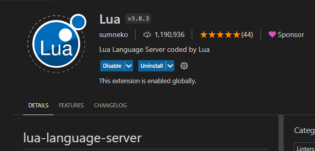
- Go to the Extensions view (click on the square icon on the sidebar or press
Ctrl+Shift+X). - Search for "Lua" and install the Lua extension by sumneko.
-
Create a Folder for Libraries
- Make a new folder on your computer to store the emdrive library. For example, you can name it
D:\LuaLibraries. - Inside the folder extract the emdrive.7z which you get directly from us.
D:\LuaLibraries\emdrive
- Make a new folder on your computer to store the emdrive library. For example, you can name it
-
Configure Developer Mode and Add Library Path
- Open Visual Studio Code.
- Press
Ctrl+Pto open the search bar. - Type
>settingsor>Open User Settings (JSON)and select "Open User Settings (JSON)" from the list.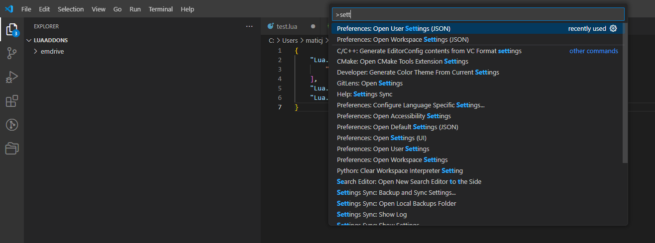
-
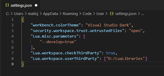
Edit User Settings (JSON)
- In the opened
settings.jsonfile, add the following code.
"Lua.misc.parameters": [ "--develop=true" ], "Lua.workspace.checkThirdParty": true, "Lua.workspace.userThirdParty": ["path_to_our_library"] - Make sure to keep any existing code intact. Add a comma at the end of the last line of the existing code, then paste the new code below it. Update the path to match your folder (
D:/LuaLibraries). Use forward slashes instead of backslashes.
- In the opened
-
Save and Close
- Save the changes to
settings.json. - Close Visual Studio Code.
- Save the changes to


Example of "settings.json":
3.2 Getting Started with Lua Scripting
3.2.1 Create "firstscript.lua"
-
Create a New Folder
- Make a new folder for your project.
-
Open the Folder with Visual Studio Code
- Right-click the folder and select "Open with Code."
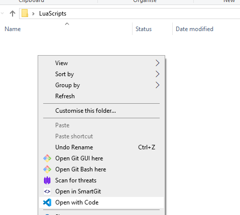
- This will open Visual Studio Code with your new folder as the workspace.
- Right-click the folder and select "Open with Code."
-
Create a New Lua Script
- In the Explorer window of Visual Studio Code, right-click and select "New File."
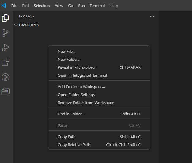
- Name the file
firstscript.lua(valid files are also "firstscript.txt", "firstscript". But it is better to use .lua which can use our emdrive Library in VS-code).
- In the Explorer window of Visual Studio Code, right-click and select "New File."


Note: Only the content of the script is transferred, not the file name.
Limitation: You can store only one script at a time on the emDrive.
3.2.2 Structure
Initialization Routine
- Function Requirement: Your script must include a function named
Initialize(). - Execution: This function is the first to run when the script is executed and runs only once.
- Purpose: Use this function to initialize hardware and firmware, such as:
- Setting up CAN
- Enabling the motor
- Setting outputs
- Setting global variables
Loop Routine
- Function Requirement: Your script must include a function named
Loop(). - Periodic Execution: This function runs periodically based on the
LoopPeriodMsvariable, which represents the period in milliseconds.- Setting the Period:
LoopPeriodMscan be set globally or within theInitialize()function.
- Setting the Period:
- Purpose: Use the
Loop()function for tasks that need regular updates, such as:- Setting motor velocity
- Parsing CAN frames
- Reading inputs and setting output ports
Minimum Loop Period: The minimum allowed loop period is 10 milliseconds.
Execution Time: Ensure the Loop() function completes within the set period to maintain deterministic execution. If the loop takes longer, it can cause unpredictable behavior.
Priority Consideration: The firmware on the emDrive has higher priority than the script, which means script execution may be interrupted by higher priority tasks.
Use the resource monitor (see the Resource Monitor section) to measure loop duration and determine the minimum possible loop period.
The resource monitor can also show the maximum loop duration when interrupted by higher priority tasks.
Data Transfer: Transferring large data over CAN/CANopen will completely block script execution.
3.3 Executing script
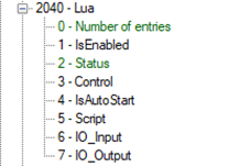
After you've created your script, it is time to download it to emDrive and execute it. For these purposes, a few CANopen objects are provided, as seen in Figure 3. They are grouped together and are accessible at index 0x2040.
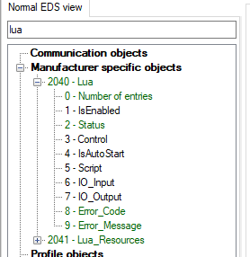
Table 52 provides a short description of objects related to script execution. More detailed meanings and use cases will be presented in the following sections.
|
Name |
Description |
|
IsEnabled |
Defines if Lua feature is enabled on particular emDrive: 0: Lua feature disabled 1: Lua feature enabled |
|
Status |
Lua status: 0: File is non-existent or corrupted, 1: Compilation failed (see Output), 2: Execution failed (see Output), 3: Downloaded file is valid, 4: Script execution is paused, 5: Script is executing, 6: Script timed out and was stopped. |
|
Control |
Lua script control: 0: Do nothing, 1: Pause, 2: Run, 3: Restart. |
|
IsAutoStart |
Should script be started automatically after device powers on? |
|
Script |
Download or upload Lua script. |
|
IO_Input |
Script input object. This object can be used to pass values/arguments to the script during runtime. |
|
IO_Output |
Script output object. This object is used to display error messages and can be used by script to print arbitrary text messages. |
|
Error_Code |
Used to show the value of error raised inside lua script. If this object is not 0, the inverter will go into error state. |
|
Error_Message |
Used to show the appropriate error description for the specific error code. |
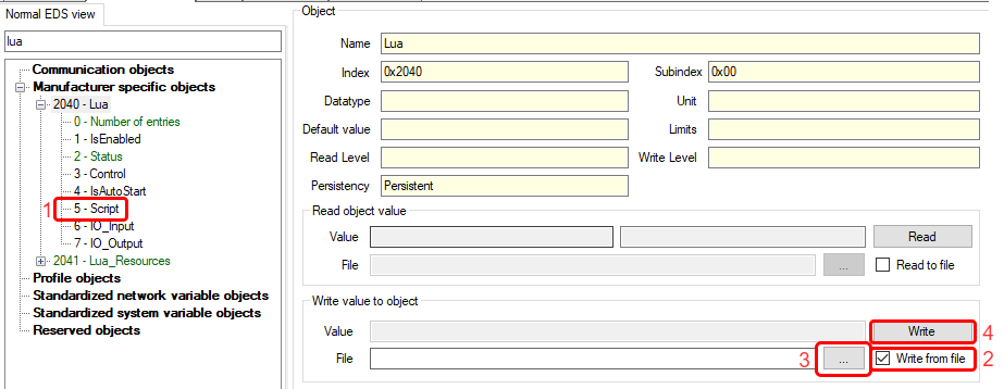
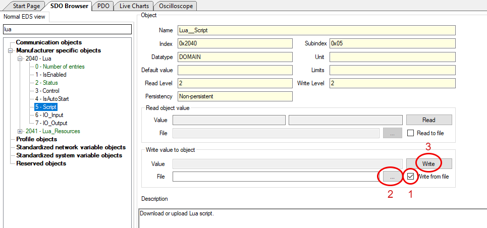
3.3.1 Download/Upload
- To download the script to emDrive
- click on Script object (0x2040, 0x5),
- check “Write from file”,
- click the “…” button which brings up an open file dialog where you select your script,
- click “Write” button which will download the script to emDrive,
- after successful download you should see a green progress bar with “Successful” label.
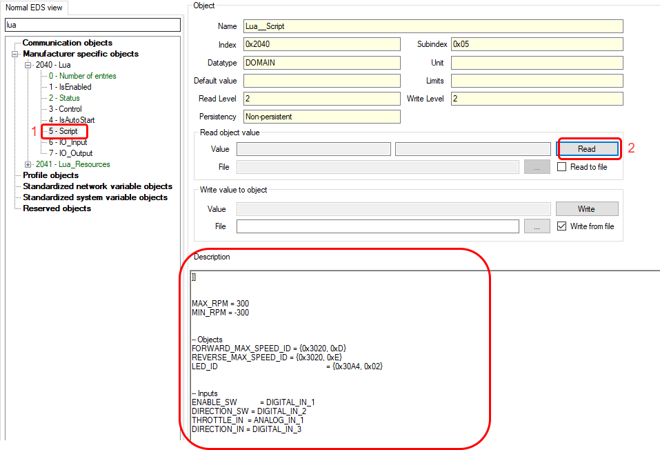
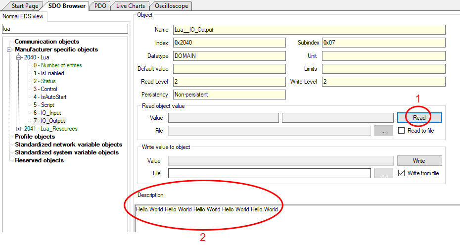
- To upload the script – this reads back the script currently stored on emDrive:
- click on Script object (0x2040, 0x5),
- click the “Read” button which will upload the script from emDrive and display it in the “Description” text box.
3.3.2 Control
Once the script has been successfully downloaded and verified, three control options become available through the Control object (0x2040, 0x3).
If a script is already executing when a new script is downloaded, the executing script is terminated as the download is initiated. After the new script is successfully downloaded and verified, it is automatically executed.
NOTE: The script is executed only after motor control has been initialized, which may delay script execution after the device powers on (usually by approximately 100 ms, although this value may vary).
3.3.3 Errors
When an error with the script is detected, the Status object (0x2040, 0x2) is set to a value signaling the type of error. There are four distinct types of errors that are detectable at different stages of script execution:
-
File is non-existent or corrupted (Status = 0): This is set when the script is not stored on the emDrive, or the stored script is corrupted. This error is triggered when script verification fails, either when the device powers on or whenever a new script is downloaded.
-
Compilation failed (Status = 1): This is set when the script could not be compiled, which could be caused by syntax errors or running out of memory. This error is triggered every time script compilation fails, such as when the script is restarted, executed for the first time, or downloaded while another script is already executing, causing the new script to be automatically compiled after downloading.
-
Execution failed (Status = 2): This is set when an error occurs during runtime—such as in initialization, loop, or other required routines—caused by several reasons like accessing nil objects, passing invalid values, missing functions, running out of memory, and others. This error is also raised if the
Error()function is called from within the script. -
Script timed out and was stopped (Status = 6): This is set when the initialization, loop, or other required routines take longer to execute than expected.
The initialization routine must execute within 100 ms, while the loop and other routines are required to execute within 2 × LoopPeriodMs.
Further details of what went wrong with the script can be retrieved from the output object.
All the above-mentioned errors are permanent. When an error is raised, emDrive protection is activated, and emDrive enters an error state from which it cannot recover (refer to the emDrive manual for more details about protections and error states). At this point, the script should be corrected for errors, downloaded to the emDrive, and then the device should be reset to clear the error.
3.3.4 Debugging
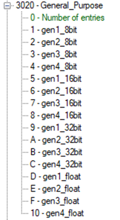
There is no proper debugging mechanism in place; however, utilizing Lua I/O objects and general-purpose CANopen objects, some form of limited debugging is possible. Using the input object, the user can control the flow of the program. The user can also write debug information to the output object. Additionally, all objects at index 0x3020, can be used freely for debugging purposes.
3.3.5 Resource monitor
The resource monitor is used to measure characteristics of the script during compile-time, initialization, and runtime (loop). All available objects relevant to resource monitoring are shown under object 0x2031 and described in Table 53.
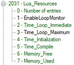
|
Name |
Description |
|
EnableLoopMonitor |
Enable loop resource monitoring which includes execution time and RAM usage. |
|
Time_Loop_Immediate |
Immediate measured loop duration [us]. |
|
Time_Loop_Maximum |
Maximum measured loop duration [us].
This value might sometimes appear unreasonably large that is when task running Lua script gets interrupted by higher priority tasks.
Write 0 to clear value and prepare it for new measurement. |
|
Time_Initialization |
Time [ms] required to execute initialization routine. |
|
Time_Compile |
Time [ms] required to load the script - that is time to script initialization. |
|
Memory_Free |
Immediately available RAM [byte]. |
|
Memory_Used |
Immediately used RAM [byte]. |
Initialization and compile-time measurements are performed every time a new script is downloaded and executed or when an existing script is restarted. Memory and loop time monitoring must be explicitly enabled by setting EnableLoopMonitor to 1. This is because these measurements are calculated every loop, thereby shortening the processing time allocated to the script.
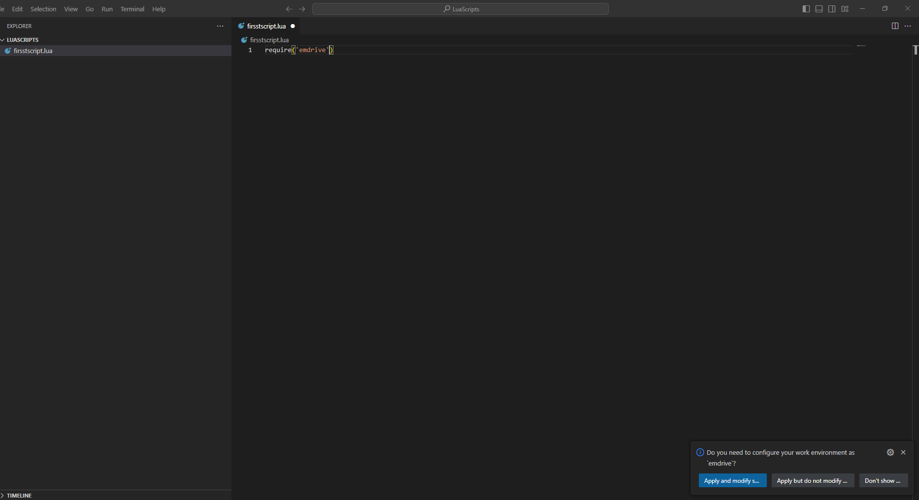
3.4 Using the emdrive Library
3.4.1 Option 1: Automatic Setup
-
Add Code to Script
- In
firstscript.lua, add the following line:
require('emdrive')
- In
-
Apply Path Modification
- A pop-up window will appear in the bottom right corner. Click "Apply and modify."
- After applying, delete the
require('emdrive')line.
-
Check .vscode Folder
- A new folder named
.vscodewill be created. - Inside, there will be a
settings.jsonfile containing the path to the library.
- A new folder named
3.4.2 Option 2: Manual Setup
-
Create .vscode Folder
- Manually create a
.vscodefolder in your workspace.
- Manually create a
-
Create settings.json File
- Inside the
.vscodefolder, create asettings.jsonfile.
- Inside the
-
Add Library Path to settings.json
- Add the following code to
settings.json:{ "lua.workspace.library": [ "D:/LuaLibraries" ] }
- Add the following code to
4. Examples
4.1 Example 1: "Hello World"
Description:
Print "Hello World" every 100ms to IO_Output.
To make the script work, you need to have two functions: Initialize and Loop.
-
Copy the Code
Copy the following code to an
example.luafile:function Initialize() LoopPeriodMs = 100 end function Loop() IO.Write("Hello World ") end -
Load the Script on the Inverter
- Go to
0x2040 0x05 - Script. - Select "Write from file" and click "...".
- A pop-up window will appear. Locate the saved script and click "Open".
- Click "Write".
- Go to
-
Check if the Script is Valid
- Go to
0x2040 0x02 - Status. - The value "3" indicates the downloaded file is valid.
- Go to
-
Run the Script
- Set
0x2040 0x03 - Controlto2. - If the script is running, the status value should be "5".
- Set
-
View the Output
- Go to
0x2040 0x07 - IO_output. - Click "Read" to see the "Hello World" string in the Description window.
- Go to
4.2 Example 2: Data types & variables
4.2.1 Example 2.1: Data types
Lua is a lightweight, high-level programming language known for its simplicity and flexibility. It has several basic data types, each serving a different purpose. Here are the main data types in Lua along with examples for each:
- Nil
Represents the absence of a value. - Boolean
Represents a boolean value, either true or false. - Number
Represents both integer and floating-point numbers. - String
Represents a sequence of characters. - Table
Represents associative arrays, which can be used as arrays, dictionaries, or other data structures. - Function
Represents a callable function.
function Initialize()
	LoopPeriodMs = 100
end

function Loop()

    -- 1. Nil
    local myVariable = nil
    IO.Print(myVariable)  -- Output: nil

    -- 2. Boolean
    local isTrue = true
    local isFalse = false
    IO.Print(isTrue)  -- Output: true
    IO.Print(isFalse)  -- Output: false

    -- 3. Number
    local integerNumber = 42
    local floatingNumber = 3.14
    IO.Print(integerNumber)  -- Output: 42
    IO.Print(floatingNumber)  -- Output: 3.14

    -- 4. String
    local myString = "Hello, Lua!"
    IO.Print(myString)  -- Output: Hello, Lua!

    -- 5. Table
    local myTable = { key1 = "value1", key2 = "value2" }
    IO.Print(myTable.key1)  -- Output: value1
    IO.Print(myTable.key2)  -- Output: value2

    local arrayTable = { "apple", "banana", "cherry" }
    IO.Print(arrayTable[1])  -- Output: apple

    -- 6. Function
    local function myFunction(a, b)
      return a + b
    end
    IO.Print(myFunction(2, 3))  -- Output: 5

    -- 6. Anonymous function
    local anonFunction = function(x, y)
      return x * y
    end
    IO.Print(anonFunction(4, 5))  -- Output: 20

end
4.2.2 Example 2.2: Variables
- Global variables
Global variables are accessible from anywhere in the program unless shadowed by a local variable of the same name. By default, any variable declared without thelocalkeyword is global.
myGlobalVariable = 10 -- Global variable function printGlobal() print(myGlobalVariable) end printGlobal() -- Output: 10 - Local Variables
Local variables are only accessible within the block or function where they are declared. They help avoid polluting the global namespace and can be used to manage scope more effectively.
local myLocalVariable = 20 -- Local variable function printLocal() local myLocalVariable = 30 -- Local to this function print(myLocalVariable) end printLocal() -- Output: 30 print(myLocalVariable) -- Output: 20 - Table fields
Variables can also be fields of tables, allowing for the creation of more complex data structures like arrays, dictionaries, and objects.
local myTable = {
  field1 = "Hello",
  field2 = "World"
}

print(myTable.field1)  -- Output: Hello
print(myTable.field2)  -- Output: World
Variable scope
- Global Scope: Variables declared outside of any function or block are global by default.
- Local Scope: Variables declared with the
localkeyword within a function, block, or loop are local to that block.
- Global vs. Local
myGlobal = "I am global" function testScope() local myLocal = "I am local" print(myGlobal) -- Accessible print(myLocal) -- Accessible end testScope() print(myGlobal) -- Accessible -- print(myLocal) -- Error: myLocal is not accessible here - Local Variable Shadowing
local x = 5  -- Local variable in the main chunk

function shadowTest()
  local x = 10  -- Local variable in the function
  print(x)  -- Output: 10
end

shadowTest()
print(x)  -- Output: 5
Global variables and tables use a lot of memory, especially in embedded systems. To save memory, it's best to use local variables whenever possible.
If you use a global variable at the start of your code and don't need it later, clear the global variable to free up memory. You can do this by adding the following code:
myGlobalVariable = nil4.3 Example 3: Inputs/Outputs
4.3.1 Example 3.1: Use of digital inputs & outputs
Turn low side 1 - ON when switch on digital pin 1 is switched ON.
function Initialize()
	LoopPeriodMs = 10
end

function Loop()

    local switch = Digital.Get(DIGITAL_IN_1)

    if switch == 1 then
        Digital.Set(LOW_SIDE_1, 1)
    else
        Digital.Set(LOW_SIDE_1, 0)
    end
end
4.3.2 Example 3.2: Use of analog inputs
Print analog value of analog input 1 when switch on digital pin 1 is switched ON.
function Initialize()
	LoopPeriodMs = 10
end

function Loop()

    local switch = Digital.Get(DIGITAL_IN_1)

    if switch == 1 then
        local rawVal = Analog.Get(ANALOG_IN_1)
        IO.Print(rawVal)
    end
end
4.4 Example 4: Blink LED
4.4.1 Example 4.1: Blink LED - "delay"
Loop period is set to 1000ms
LED is connected on low side 1.
Blink LED every 0.5s with Time.WaitMs().
function Initialize()
	LoopPeriodMs = 1000
end

function Loop()

    local ledState = Digital.Get(LOW_SIDE_1)

    if(ledState == 0) then
        Digital.Set(LOW_SIDE_1, 1)
    else
        Digital.Set(LOW_SIDE_1, 0)
    end

    Time.WaitMs(500)

end
If we set the LoopPeriodMs to 100ms, the script stops running and shows a status of "6", meaning "Script timed out and was stopped."
Here are the key points to understand:
- Time.WaitMs() Function: This function pauses the script for a specified time. In our example, it pauses for 0.5 seconds.
- LoopPeriodMs Setting: We set the script to loop every 100ms.
- Error Explanation: Since the script must loop every 100ms but pauses for 0.5 seconds, it causes an error.
Important Note: Be very careful when using the Time.WaitMs() function to avoid such errors.
4.4.2 Example 4.2: Blink LED - using loop time
We want the LED to blink every 0.5 seconds, while the main loop runs every 10ms. Here's how we do it:
Main_loop_period = 10
Counter = 1


function Initialize()
	LoopPeriodMs = Main_loop_period
end

function Loop()

    if ((Counter)*Main_loop_period)%500==0 then

        local ledState = Digital.Get(LOW_SIDE_1)

        if(ledState == 0) then
            Digital.Set(LOW_SIDE_1, 1)
        else
            Digital.Set(LOW_SIDE_1, 0)
        end

    end

    if Counter<50 then
        Counter=Counter+1
    else
        Counter=1
    end

end
4.4.3 Example 4.3: Blink LED - using processor time
The script initializes a start time variable and defines two functions. In the Loop function, the script checks if the StartTime is nil and if so, sets it to the current time in milliseconds.
The Loop function then continuously gets the current time in milliseconds. If 500 milliseconds have passed since the StartTime, it resets the StartTime to the current time.
It then gets the state of a digital output LOW_SIDE_1.
If LOW_SIDE_1 is off (state is 0.0), it turns it on (state to 1.0).
If LOW_SIDE_1 is on (state is 1.0), it turns it off (state to 0.0).
This process repeats every 500 milliseconds, toggling the state of LOW_SIDE_1 each time.
StartTime = nil

function Initialize()
	LoopPeriodMs = 10
end

function Loop()

    --Execute only once at the start of the loop
    if(StartTime == nil) then
        StartTime = Time.GetMs()
    end

    --Chechk every loop what is the time
    local CurrentTime = Time.GetMs()

    if (CurrentTime - StartTime >= 500) then
        StartTime = CurrentTime

        local ledState = Digital.Get(LOW_SIDE_1)

        if(ledState == 0) then
            Digital.Set(LOW_SIDE_1, 1)
        else
            Digital.Set(LOW_SIDE_1, 0)
        end

    end
end
4.5 Example 5: CAN send
4.5.1 Example 5.1: (CAN send simple message)
To send a CAN message every 100ms with an ID of 0x205 and data value 500 using the first 2 bytes, follow these steps:
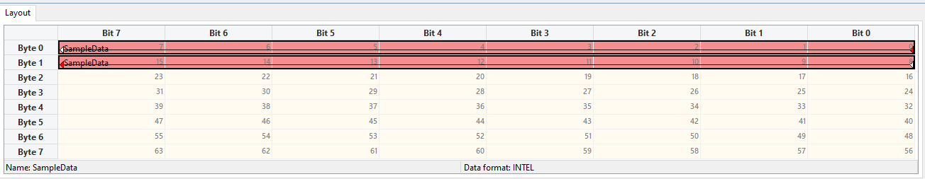
-
Use Template:
- Start with example 4.3 as a template.
-
Add Variables and Functions:
- Define a
CanIDvariable. - Initialize CAN with the
CAN.Initialize()function.
- Define a
-
Sending Parameters:
- Use the
CAN_TX_ONLYparameter for sending. - Messages will not be extended.
- Set filters to 0 since we are only sending.
- Use the
-
Modify the Code:
- Delete the code for toggling the output.
-
Create Custom Function:
- Create a function that is called every 100ms.
- Name the argument
Data_raw. - Split
Data_rawinto 2 bytes. - Send the data using the
CAN.Send()function.
CanID = 0x205

StartTime = nil

function Initialize()

    CAN.Initialize(CAN_TX_ONLY,false,0,0)

	LoopPeriodMs = 10
end

function Loop()

    --Execute only once at the start of the loop
    if(StartTime == nil) then
        StartTime = Time.GetMs()
    end

    --Chechk every loop what is the time
    local CurrentTime = Time.GetMs()

    if (CurrentTime - StartTime >= 100) then
        StartTime = CurrentTime
        SendData(500)
    end
end

function SendData(Data_raw)
    local val = Data_raw
    local byte0 = math.floor(val) & 0xFF
    local byte1 = (math.floor(val) & 0xFF00) >> 8
    CAN.Send(CanID,{byte0,byte1,0,0,0,0,0,0})
end
In this example we only need 2 bytes, thus we don't need to send all 8 bytes out. You could do this instead:
CAN.Send(CanID,{byte0,byte1})4.5.2 Example 5.2 : CAN send extended message (J1939)
We will do the same as in example 5.1 except we will send an extended message (It will be a J1939 message PH3 - the data order might be different in the standard).
ID = 0x18FF8203.
The only thing we need to change is 2 lines, we need to change the CanID and in the CAN.Initialize() function, the boolean value to true. If we change only the CanID then the message will still be sent out but the ID will be 0x199 (last 3 digits of - ID 0x18FF8199).
CanID = 0x18FF8199
CAN.Initialize(CAN_TX_ONLY,true,0,0)
4.6 Example 6: CAN receive
4.6.1 Example 6.1 : CAN receive
In this example we will turn ON and OFF a LED that is connected on low side 1 with a received can message.
The Can ID has to be 0x123 and we will send only one byte of data. If the value of data is 1 then the LED will be turned ON, otherwise it will be turned OFF.
To use the CAN receive function we need to change the CAN.Initialite() and add a function called "CAN.Received(message)". With the following code we always go into the CAN.Received() function when a message is received and then we check if the ID is correct.
function Initialize()
    CAN.Initialize(CAN_RX_TX,false,0,0)
	LoopPeriodMs = 10
end

function Loop()


end

function CAN.Received(message)
    if (message.ID == 0x123) then
        IO.Print(" Data1: ", message.Data[1])
        if(message.Data[1] == 1) then
            Digital.Set(LOW_SIDE_1, 1)
        else
            Digital.Set(LOW_SIDE_1, 0)
        end
    end
end
We can also add a filter so we only go into the CAN.Received() when the message has a proper ID. We achieve this with the following code.
function Initialize()
    CAN.Initialize(CAN_RX_TX,false,0x123,0x123)
	LoopPeriodMs = 10
end

function Loop()


end

function CAN.Received(message)
    --if (message.ID == 0x123) then
    IO.Print(" Data1: ", message.Data[1])
    if(message.Data[1] == 1) then
        Digital.Set(LOW_SIDE_1, 1)
    else
        Digital.Set(LOW_SIDE_1, 0)
    end
    --end
end
4.7 Example 7: Read & Set CANopen objects
In this example, we'll use an analog input (HW AIN1) as a throttle to set the motor velocity reference (object 0x3010 0x05). We will also read this object and print its value to the Lua output. Additionally, we'll limit the maximum RPM using the math library to prevent the motor from running away if there's a problem with the analog reading.
0V = 0RPM
5V = 200RPM
For this example to work you need an inverter that is configured to work with the connected motor. You need to be first able to spin it in velocity mode using the configurator.
When you start the script go to operational and turn on PWMs manually.
If the analog throttle is damaged (either a short circuit or a broken circuit), there is no safety system in place. Here’s what can happen:
If the circuit is broken, no voltage will be applied, and the RPM will be 0.
If there is a short circuit, the inverter will receive the full 5V on the analog input, causing the RPM to go to the maximum.
To prevent these issues, we need to add safety features. These will be demonstrated in Example 8.
VelocityRef = {0x3010, 0x05}

function Initialize()
	LoopPeriodMs = 10
end

function Loop()


    local rpm = Analog.Get(ANALOG_IN_1) * 40
    rpm = math.min(rpm,200)

    CANopen.SetObjectValue(VelocityRef, rpm)

    local VelRef_from_CANopen = CANopen.GetObjectValue(VelocityRef)

    IO.Print(VelRef_from_CANopen)
end
4.8 Example 8: Demo application
4.8.1 Example 8.1 : Demo application using CANopen objects.
In this example, we will demonstrate how to use the HW AIN1 input for a simple throttle control with a potentiometer (0-5V).
- Throttle Input: HW AIN1 (0-5V Potentiometer)
- Minimum RPM: 0 (corresponds to 0.5V)
- Maximum RPM: 200 (corresponds to 4.5V)
- Motor Stop Conditions:
- If the throttle voltage is below 0.2V or above 4.8V, the motor will stop to protect against short and break issues.
- PWM Enable Condition:
- If the throttle voltage is below 0.5V, the PWM signals will be enabled
function Initialize()

    CANopen.SetObjectValue(VelocityRef, 0) -- Set Velocity ref to 0
	CANopen.SetObjectValue(ControlMode, 1) -- Set velocity mode
	CANopen.SetNMTState(CO_OPERATIONAL)    -- Go into operational mode

	LoopPeriodMs = 100
end

function Loop()
    local throttleVoltage = Analog.Get(ANALOG_IN_1)
    -- Decide whether to enable or disable the motor
    if Digital.Get(DIGITAL_IN_1) == 1 then
        -- only enable if voltage on 0.2 < ANALOG_IN_1 < 0.5 V so the motor does not start ang goes to high RPM
        if  (0.2 < throttleVoltage and throttleVoltage < 0.5) then
            CANopen.SetObjectValue(PwmControl, 1)
        end
    else
        CANopen.SetObjectValue(PwmControl, 0)
    end

    if (throttleVoltage > 0.2 and throttleVoltage < 4.8) == true then
           -- Map values 0.5 - 4.5 V to 0 - 200 RPM and
            local rpm = (throttleVoltage - 0.5) / 4 * 200
            rpm = math.min(rpm, 200)
            rpm = math.max(rpm, 0)
            CANopen.SetObjectValue(VelocityRef, rpm)
    else
        CANopen.SetObjectValue(VelocityRef, 0)
        CANopen.SetObjectValue(PwmControl, 0)
    end
end
4.8.2 Example 8.2 : Demo application using dedicated motor library.
In this example we will have the same functionality of the code as in example 8.1. but with the use of motor library
With the use of the motor library the code is easier to read and write than example 8.1.
function Initialize()

    Motor.SetReferenceVelocity(0)       -- Set Velocity ref to 0
	Motor.SetControlMode(VELOCITY_MODE) -- Set velocity mode
	CANopen.SetNMTState(CO_OPERATIONAL) -- Go into operational mode

	LoopPeriodMs = 100
end

function Loop()
    local throttleVoltage = Analog.Get(ANALOG_IN_1)
    -- Decide whether to enable or disable the motor
    if Digital.Get(DIGITAL_IN_1) == 1 then
        -- only enable if voltage on 0.2 < ANALOG_IN_1 < 0.5 V so the motor does not start ang goes to high RPM
        if  (0.2 < throttleVoltage and throttleVoltage < 0.5) then
            Motor.Enable()
        end
    else
        Motor.Disable()
    end

    if (throttleVoltage > 0.2 and throttleVoltage < 4.8) == true then
           -- Map values 0.5 - 4.5 V to 0 - 200 RPM and
            local rpm = (throttleVoltage - 0.5) / 4 * 200
            rpm = math.min(rpm, 200)
            rpm = math.max(rpm, 0)
            Motor.SetReferenceVelocity(rpm)
    else
        Motor.SetReferenceVelocity(0)
        Motor.Disable()
    end
end
4.9 Example 9: Throttle script (state - machine)
Throttle Control
- Adjusting the Throttle: Use the potentiometer connected to Analog_IN_1.
- Protection: The potentiometer is protected against short and break circuits.
- Deadband: A deadband of 0.3V is set for the potentiometer.
- Speed Limits (needs to be set in objects described below):
- Minimum speed: 0 RPM
- Maximum speed: 300 RPM
Motor Operation
- Activation:
- The motor runs only when digital pin 1 (ON/OFF switch) is connected.
- Change motor direction using a switch on digital pin 3.
- Speed Setting:
-
Forward max speed: Object 0x3020 0x0D
-
Reverse max speed: Object 0x3020 0x0E
- Switching direction at max speed changes to the corresponding reverse speed.
-
LED Diagnostics
- LED Indicator (HS1):
- On: System working normally.
- Blinking: System in error mode.
- Error Blink Codes:
- Error 2: Blinks twice, then pauses.
- Error 3: Blinks three times, then pauses.
Voltage and RPM Details
- Working Voltage Range:
- Minimum RPM: at 0.5V
- Maximum RPM: at 4.5V
- Deadband: 0.3V
- Error Conditions:
- ERROR1: Voltage out of bounds
- ERROR2: Analog_IN_1 < (Min_Volt - Deadband)
- ERROR3: Analog_IN_1 > (Max_Volt + Deadband)
CANopen Error Messages
- Error Message (0x80 + nodeID):
- Sent every 100ms in error state.
- Data length: 8 bytes.
- Byte 0 Mapping:
- Bit 0: Throttle potentiometer error out of bounds
- Bit 1: Throttle potentiometer break circuit error
- Bit 2: Throttle potentiometer short circuit error
- Warning Message (0x180 + nodeID):
- Sent every 100ms in start state.
- Data length: 8 bytes.
- Byte 0: Warning code 0x01 (Motor disabled, potentiometer not in min position)
If the motor spins at Forward max speed and you switch the direction with the switch then it will spin at Reverse max speed
-- Limits
MAX_RPM = 300
MIN_RPM = -300

-- Objects
FORWARD_MAX_SPEED_ID = {0x3020, 0xD}
REVERSE_MAX_SPEED_ID = {0x3020, 0xE}
LED_ID 				 = {0x30A4, 0x02}


-- Inputs
ENABLE_SW 	 = DIGITAL_IN_1
DIRECTION_SW = DIGITAL_IN_2
THROTTLE_IN  = ANALOG_IN_1
DIRECTION_IN = DIGITAL_IN_3


-- Voltage thresholds
THROTTLE_MIN_V = 0.5
THROTTLE_MAX_V = 4.5
DEADBAND 	 = 0.3


ERROR	  = 0
ERROR_reg = 0
WARNINGS  = 0


StartTime1	= nil
StartTIme2	= nil
StartTime3 	= nil
StartTime4 	= nil
FlagCounter = 0


DIN		  = {ON = 1, OFF = 0}
LED 	  = {OFF = 0x0, ON = 0x1}
DIRECTION = {FORWARD = 1, REVERSE = 0}

-- Application FSM
Application = {}


function Initialize()
	CAN.Initialize(CAN_TX_ONLY,false,0,0)

	Application.NextState = "Idle"

    Motor.SetReferenceVelocity(0)
	Motor.SetControlMode(VELOCITY_MODE)

	LoopPeriodMs = 10
end


function Loop()
	Application[Application.NextState]()
end


Application.Idle = function ()
	CANopen.SetObjectValue(LED_ID, LED.ON)
	CANopen.SetNMTState(CO_OPERATIONAL)
	Application.NextState = "Start"
end


Application.Start = function ()


    -- IF enable switch is off go to stop state
    if (Digital.Get(ENABLE_SW) == DIN.OFF ) then
		Application.NextState = "Stop"
		return
	end


    -- Get voltage
	local throttleVoltage = Analog.Get(THROTTLE_IN)


    -- Go into error state if throttle voltage is out of bounds
    if OutOfBounds(throttleVoltage, (THROTTLE_MIN_V - DEADBAND), (THROTTLE_MAX_V + DEADBAND)) == true then
		ERROR = (ERROR or 0) | 1
		Application.NextState = "Error"
		return
	end


    -- Check that voltage is bellow minimal throttle voltage - so that the motor does not start at high speed
	if Motor.GetState() == MOTOR_OFF then
		if throttleVoltage < (THROTTLE_MIN_V) then
            Motor.Enable()
			WARNINGS = WARNINGS & Negate_Xbit(1, 8)
            return
		else
			WARNINGS = (WARNINGS or 0) | 1
        end
	end

	-- Only set velocity reference when pwms are enabled
	if ((Motor.GetState() == MOTOR_RUN) and (throttleVoltage >= 0.5)) then
		-- Calculate Voltage
    	--local rpm = ((throttleVoltage - THROTTLE_MIN_V) * MAX_RPM) / (THROTTLE_MAX_V - THROTTLE_MIN_V)
		local rpm = ((throttleVoltage - THROTTLE_MIN_V) * GetMaxSpeed()) / (THROTTLE_MAX_V - THROTTLE_MIN_V)
    	-- Limit RPM
    	rpm = math.min(rpm, MAX_RPM)
    	rpm = math.max(rpm, MIN_RPM)
		IO.Print("REF: ", rpm)
    	-- Set ref
		Motor.SetReferenceVelocity(rpm)
	end

	-- Send warnings every 100ms
	local CurrentTime = Time.GetMs()
	if((StartTIme2 == nil) or (CurrentTime-StartTIme2) >= 100) then
		SendWarnings()
	end
end


Application.Stop = function ()
    Motor.SetReferenceVelocity(0)
	Motor.Disable()
    --When eneble sw is activated go to start state
	if (Digital.Get(ENABLE_SW) == DIN.ON) then
		Application.NextState = "Start"
	end
end

Application.Error = function ()

    Motor.Disable()
	Motor.SetReferenceVelocity(0)

	--local ledValue = CANopen.GetObjectValue(LED_ID)
    local throttleVoltage = Analog.Get(THROTTLE_IN)
	local ErrorBlinkCounter = 0
	local CurrentTime

	--If bit 0 = 1 then OutOfBounds is detected
	if (ERROR & 1) == 1 then
		if throttleVoltage < (THROTTLE_MIN_V - DEADBAND) then
			ERROR = ERROR | 2
			ERROR_reg = ERROR_reg | 1 -- set the generic error register
		elseif throttleVoltage > (THROTTLE_MAX_V + DEADBAND) then
			ERROR = ERROR | 4
			ERROR_reg = ERROR_reg | 1 -- set the generic error register
		else
			-- Clear ERROR bit 0, 1, 2
			ERROR = ERROR & Negate_Xbit(7, 16)
			-- Clear the generic error register
			ERROR_reg = ERROR_reg | Negate_Xbit(1, 8)
		end
	end

	-- Send Errors every 100ms
	CurrentTime = Time.GetMs()
	if ((StartTime1 == nil) or (CurrentTime - StartTime1) >= 100) then
		StartTime1 = CurrentTime
		SendError()
	end

	-- Determine how many times we want to blink the led
    if ((ERROR & 2) >> 1) == 1 then
        ErrorBlinkCounter = 2
    elseif ((ERROR & 4) >> 2) == 1 then
        ErrorBlinkCounter = 3
    end

    -- Start the blinking cycle if enough time has passed
	CurrentTime = Time.GetMs()
    if StartTime3 == nil or (CurrentTime - StartTime3) >= 3000 then
        StartTime3 = CurrentTime
        FlagCounter = 0
    end

    -- Handle the blinking logic
    if FlagCounter < 2 * ErrorBlinkCounter then
        if StartTime4 == nil or (CurrentTime - StartTime4) >= 300 then
            StartTime4 = CurrentTime
            FlagCounter = FlagCounter + 1

            -- Toggle LED
            --if ledValue == 0  then
            if FlagCounter % 2 == 1 then
				CANopen.SetObjectValue(LED_ID, LED.ON)
            else
                CANopen.SetObjectValue(LED_ID, LED.OFF)
            end
        end
	else
		-- Ensure the LED is off during the pause period
        CANopen.SetObjectValue(LED_ID, LED.OFF)
    end

    if ERROR == 0 then
		FlagCounter = 0
		Application.NextState = "Idle"
		return
	end
end


function GetMaxSpeed()
	if Digital.Get(DIRECTION_IN) == DIRECTION.FORWARD then
		return CANopen.GetObjectValue(FORWARD_MAX_SPEED_ID)
	end
	return CANopen.GetObjectValue(REVERSE_MAX_SPEED_ID)
end


function SendError()
	-- Send on ID + nodeID; we get the NodeId from CANopen off the inverter
	local CanID = 0x80 + CANopen.GetObjectValue({0x100B, 0x00})
	local byte0 = ERROR & 0xFF
	local byte1 = (ERROR & 0xFF00) >> 8
	local byte2 = ERROR_reg & 0xFF
	CAN.Send(CanID,{byte0, byte1, byte2, 0, 0, 0, 0, 0})
end

function SendWarnings()
	-- Send on PDO + nodeID;
	local CanID = 0x180 + CANopen.GetObjectValue({0x100B, 0x00})
	local byte0 = WARNINGS & 0xFF
	CAN.Send(CanID,{byte0, 0, 0, 0, 0, 0, 0, 0})
end


function OutOfBounds(throttleVoltage, minVal, maxVal)
    if (throttleVoltage < minVal) or (throttleVoltage > maxVal) then
        return true
    else
        return false
    end
end


--- Fuctino to negate bits
---@param value number Value to negate
---@param xBit number Number of bites e.g 16bit => xBit = 16
function Negate_Xbit(value, xBit)
    local negated = 0
    for i = 0, (xBit - 1) do
        if (value & (1 << i)) == 0 then
            negated = negated + (1 << i)
        end
    end
    return negated
end
4.10 Example 10: Read protections of motor control in Lua
Purpose:
This script is designed to monitor and report various hardware errors in motor control systems, using Lua to check status registers for issues such as overtemperature, voltage discrepancies, and communication failures.
Description:
- Protection_bits Table: Lists each error with a unique bitmask for identification.
- Initialize Function: Sets initial conditions, including the loop frequency.
- Loop Function: Repeatedly retrieves the current error status, checks each potential error against the current status, and prints messages for any active errors.
Usage:
It is best to use only the protections that you need to check or send. By doing this, you can make the Protection_bits table smaller, which in turn reduces memory usage—a crucial consideration in environments with limited resources. Either way, if the value returned from the function is greater than 0, an error has occurred.
local Errors = {}
local Protection_bits = {
    {0x1, "sw_phase_error"},
    {0x2, "sw_DC_link_overvoltage_error"},
    {0x4, "sw_DC_link_undervoltage_error"},
    {0x8, "bridge_overtemperature_error"},
    {0x10, "capacitor_overtemperature_error"},
    {0x20, "motor_overtemperature_error"},
    {0x40, "current_offset_error"},
    {0x80, "CAN_command_timeout_error"},
    {0x100, "system_self_test_failed_error"},
    {0x800, "motor_feedback_error"},
    {0x8000, "CAN_communication_error"},
    {0x10000, "logic_supply_monitor_error"},
    {0x20000, "dc_link_overvoltage_comparator_error"},
    {0x80000, "gatedriver_error"},
    {0x100000, "HV_interlock"},
    {0x200000, "motor_temperature_sensor_fail"},
    {0x400000, "capacitor_temperature_sensor_fail"},
    {0x800000, "bridge_temperature_sensor_fail"},
    {0x1000000, "bridge_fault"},
    {0x2000000, "logic_supply_fault"},
    {0x4000000, "bus_bar_fault"},
    {0x8000000, "system_initialization_error"},
    {0x10000000, "fault_Vrefs_chip"},
    {0x20000000, "application_error_state"},
    {0x40000000, "motor_control_error"}
    --{0x80000000, "error_extended"}
}

-- Initialize
function Initialize()
    LoopPeriodMs = 10
end

function Loop()
    local protections = Motor.GetProtectionsLow()

    for i = 1, #Protection_bits do
        local bitmask = Protection_bits[i][1]
        local varname = Protection_bits[i][2]
        Errors[i] = {bitmask = bitmask, name = varname, state = (protections & bitmask) == bitmask}
    end

    -- Example usage to print all active errors
    for i = 1, #Errors do
        if Errors[i].state then
            IO.Print("Error detected: " .. Errors[i].name)
        end
    end
end
5. Benchmark
5.1 Examples for benchmark:
5.1.1 00_Empty_script
function Initialize()
	LoopPeriodMs = 10
end

function Loop()
end
5.1.2 01_GetObject
function Initialize()
	LoopPeriodMs = 10
end

function Loop()
	for i = 1,100 do
		CANopen.GetObjectValue({0x30B0, 0x04})
	end
end
5.1.3 02_GetObject_with_library
function Initialize()
	LoopPeriodMs = 10
end

function Loop()
	for i = 1,100 do
		Digital.Get(DIGITAL_IN_4)
	end
end
5.1.4 03_GetSet
function Initialize()
	LoopPeriodMs = 10
end

function Loop()
	for i = 1,50 do
		local throttle = CANopen.GetObjectValue({0x3090, 0x01})
		CANopen.SetObjectValue({0x3010, 0x05}, throttle * 40) --at 4.5V = 180RPM
	end
end
5.1.5 04_GetSet_with_library
function Initialize()
	LoopPeriodMs = 10
end

function Loop()
	for i = 1,50 do
		local throttle = Analog.Get(ANALOG_IN_1)
		Motor.SetReferenceVelocity(throttle * 40) --at 4.5V = 180RPM
	end
end
5.2 Results
We loaded each script onto the inverter and started the "Resource Manager." We ran the script for a specific period and logged the variables to a live chart, from which we then created the following table:
Examples from 05 onwards can be found under the title 4. Examples.
|
Name of script |
RAM usage [kB] |
RAM free |
RAM used |
Avg. loop duration [us] |
Compile time [ms] |
Initialization time [ms] |
| 00_Empty_script | 11.800 |
24.040 |
33 | 13 | 2.7 | 0.175 |
| 01_GetObject | 11.728 | 24.112 | 33 | 5000 | 2.9 | 0.173 |
| 02_GetObject_with_library | 11.784 | 24.056 | 33 | 510 | 2.94 | 0.241 |
| 03_GetSet | 12.088 | 23.752 | 34 | 5000 | 3.178 | 0.177 |
| 04_GetSet_with_library | 12.128 | 23.712 | 34 | 450 | 3.149 | 0.174 |
| 05_Timer_example_4_1 | 12.064 | 23.776 | 34 | 500407 | 3.294 | 0.242 |
| 06_Timer_example_4_2 | 12.200 | 23.640 | 34 | 17 | 3.669 | 0.177 |
| 07_Timer_example_4_3 | 12.232 | 23.608 | 34 | 19 | 3.747 | 0.175 |
| 08_Example_5 | 12.104 | 23.736 | 34 | 18 | 4.332 | 0.213 |
| 09_Example_6 | 15.512 | 20.328 | 43 | 9 | 3.468 | 0.225 |
| 10_Example_7 | 22.048 | 12.792 | 63 | 125 | 3.506 | 0.191 |
| 11_Example_8_1 | 13.472 | 22.368 | 38 | 110 | 5.030 | 0.293 |
| 12_Example_8_2 | 13.072 | 22.768 | 36 | 50 | 4.628 | 0.250 |
| 13_Example_9 | 21.112 | 14.728 | 59 | 250 |
15.756 |
0.742 |
![Ram used [%]](http://help.emsiso.com/uploads/images/gallery/2024-07/embedded-image-3chsvi0d.png)
![Average loop time [us]](http://help.emsiso.com/uploads/images/gallery/2024-07/embedded-image-znzcz6k9.png)
Examples 01, 03, and 05 have too much loop time and were excluded from the chart.
As you can see from the table and charts, reading and writing values directly from the CANopen stack takes longer than using our library. For example, the 01_GetObject example has an average loop time execution of 5ms, whereas the 02_GetObject_with_library example has an average time of 510µs, which is approximately 10 times faster. Based on these results, it is better to use functions that directly interact with the inverter instead of the CANopen stack, where possible.
We can also see that the delay function used in example 05_Timer_example_4_1 has a very long loop time because we used the delay to blink an LED. This function must be used with caution and only for small delays if you have no other option.
For writing applications, we recommend using a state machine, which is more reliable. With a state machine, you have more control over what happens in each state and can properly define the transitions between states.
In section "5.3 Live chart data for each example", we can see the loop time, RAM used and RAM free for a specific time period. We can se that we have some spikes in loop time, which can indicate that some specific part of the code was executed or that the script was interrupted with a higher priority task. We can also see that the RAM usage can very based on which part of the code is executed.
5.3 Global variables benchmark
In this section, we will demonstrate how the number of global variables affects script RAM usage and loop execution time.
Below is the code that will be used to test 10 global variables. We will increase the number of global variables to 20, 30, 100, and 150, but the principle will remain the same
Global1 = 1
Global2 = 1
Global3 = 1
Global4 = 1
Global5 = 1
Global6 = 1
Global7 = 1
Global8 = 1
Global9 = 1
Global10 = 1

function Initialize()
	LoopPeriodMs = 10
end

function Loop()
  IO.Print(Global1)
  IO.Print(Global2)
  IO.Print(Global3)
  IO.Print(Global4)
  IO.Print(Global5)
  IO.Print(Global6)
  IO.Print(Global7)
  IO.Print(Global8)
  IO.Print(Global9)
  IO.Print(Global10)
end
In the table below, we recorded the data for different sets of global variables. We can observe that as the number of global variables increases, the compile time, initialization time, loop execution time, and RAM usage all increase. It is important to remember that we are limited by the loop execution time set in the initialize() function. If we exceed that time, we encounter an error.
More importantly, we need to carefully manage the number of global variables because excessive use can lead to memory overflow. As shown in the table below, having 150 global variables consumes around 75% of the RAM, but our code has almost no functionality. If we add the following code right after the Loop() function:
for i = 1,50 do
		local throttle = CANopen.GetObjectValue({0x3090, 0x01})
		CANopen.SetObjectValue({0x3010, 0x05}, throttle * 40) --at 4.5V = 180RPM
end
We see that the RAM usage jumps to 98%. This shows that RAM usage depends not only on the number of global variables but also on the quality of the code itself. Therefore, we need to write efficient code, which means avoiding the use of global variables, using local variables, and implementing proper algorithms.
For these reasons, it is difficult to specify the maximum number of global and local variables. We recommend testing your script continuously during development.
|
Number of globals |
RAM usage [kB] |
RAM free |
RAM used |
Avg. loop duration [us] |
Compile time [ms] |
Initialization time [ms] |
| 10 globals |
12.656 | 23.184 | 35 | 200 | 3.874 | 0.257 |
| 20 globals | 14.480 | 21.360 | 40 | 380 | 4.942 | 0.412 |
| 30 globals | 14.688 | 21.152 | 41 | 650 | 6.018 | 0.591 |
| 100 globals | 25.408 | 10.432 | 71 | 2000 | 13.5 | 0.795 |
| 150 globals | 26.976 | 8.864 | 75 | 3110 | 18.4 | 1.276 |
| 150 globals + 4 lines of code | 35.072 | 768 | 98 | 8000 | 18.9 | 1.213 |
6. Best practices
For further insights and practical tips, I recommend exploring "Programming in Lua," available at: Programming in Lua. Authored by experts in the field, this comprehensive resource offers invaluable guidance for Lua developers. It's worth noting that the entire topic is accessible free of charge as of April 24, 2024. Additionally, some sections of the topic include examples to further illustrate key concepts and techniques.
6.1 Minimizing Global Variables
The most common problem with Lua scripting occurs when the script becomes "big" and the programmer uses only or to much global, resulting in an "out of memory" error. In Lua scripting, it's imperative to exercise caution with global variables to prevent memory exhaustion and script failures, especially on embedded systems. Emphasizing the utilization of local variables whenever possible is paramount. By minimizing global variable usage, we mitigate the risk of memory overflow and enhance script performance.
7. Known issues and limitations
This section describes known issues and limitations, their causes, and solutions or mitigations if they exist.
7.1 Issues
7.1.1 Lua is not enabled
Error 0x06070010 when loading a script may indicate Lua object 0x2040 0x01 isn't set to 1. To resolve, ensure proper access level in Configurator to unlock this feature. If you do not have the proper access level contact us.
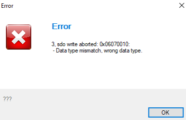
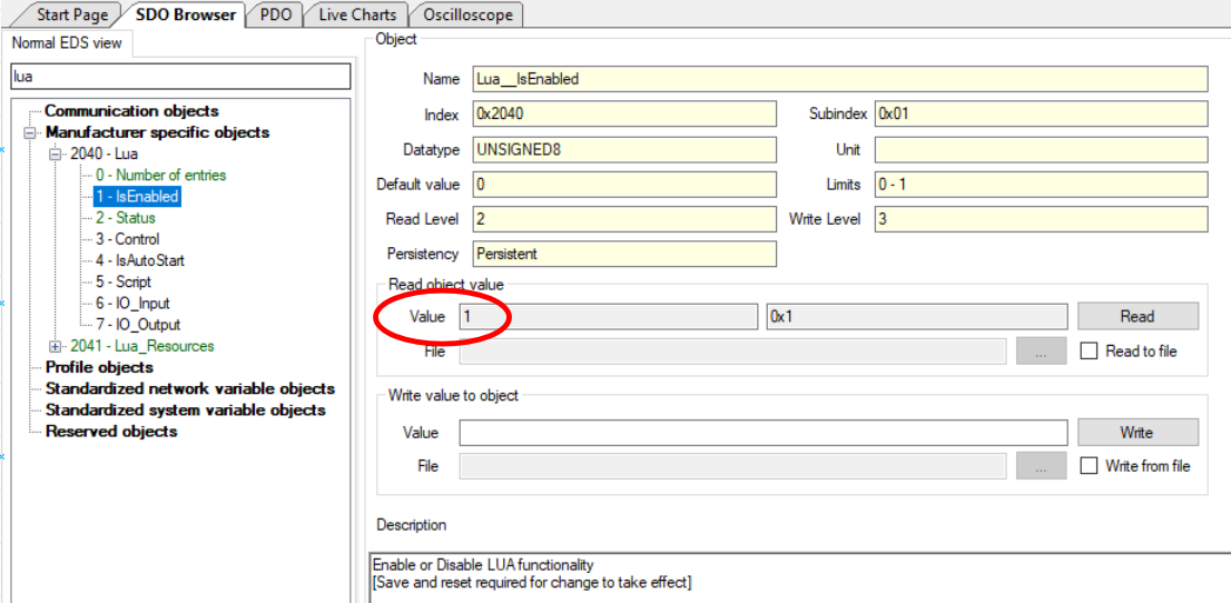
7.1.2 Output object out of memory error
When reading an output object whose value is periodically changing by the script, it is possible that an "Out of memory" error, as shown in Figure 8, may be reported by the emDrive Configurator.
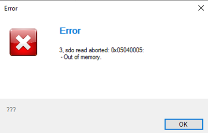
Cause: unsynchronized reading and writing to output object by script and emDrive Configurator at the same time.
Solution: read output object again.
7.1.3 IO.Print() isn't functioning
If IO.Print() isn't functioning, it may signal an outdated firmware version. FW 1.12.2 - lacks support, while FW 1.13.2 onwards enables the function.
7.1.4 Protections
If multiple protections are active, the CANopen read wont work for the protection object. (New FW will fix this issue)
Throttle Application Manual
Disclaimer
Proprietary Information: This manual contains proprietary information belonging to Emsiso d.o.o. The text and graphics included are for illustration and reference purposes only. Specifications are subject to change without notice.
Scope of Application: The Throttle Application is designed for integration with emDrive systems. Users should ensure compatibility with their specific hardware and software configurations.
User Responsibility: Proper installation, configuration, and operation of the Throttle Application require technical expertise. Users must adhere to all safety guidelines and operational instructions provided in this manual.
Updates and Revisions: Emsiso d.o.o. reserves the right to modify the product and manual without prior notice. Users are encouraged to consult the latest version of the manual for up-to-date information.
Liability Disclaimer: Emsiso d.o.o. assumes no liability for damages resulting from the use or misuse of the Throttle Application, including but not limited to personal injury, equipment damage, or financial loss.
By using the Throttle Application, you acknowledge that you have read, understood, and agreed to these terms and conditions
1. Introduction
1.1 Overview
The Throttle application allows the user to implement a simple throttle control directly on the emDrive. Input devices can be connected directly to the emDrive and mapped to the throttle application. The application calculates the desired output based on these inputs and passes it to motor control. The output can be used as either a torque input or a speed input in the motor controller, depending on which CANOpen object the output is mapped to.
1.2 Features
The Throttle application supports the following features:
- Throttle Module
Functionality: Calculates the desired output based on mapped input and configuration parameters.
Capabilities: Can be configured as unidirectional or bidirectional. - Brake Module
Functionality: Calculates the desired brake torque based on mapped input and configuration parameters.
Capabilities: Unidirectional only, with brake torque always in the opposite direction to motor rotation.If the desired output is speed, the brake should be disabled as this module is intended to be used for torque control.
- Pump Control Module
Functionality: Controls the pump, turning it on or off depending on motor and drive temperature. - Precharge Module
Functionality: Manages the precharge process at startup. - DC-DC Turn on Delay Module
Functionality: Delays the activation of the DC-DC converter after startup to ensure controlled power application. - SOC Monitoring Module
Functionality: Monitors the State of Charge (SOC) of the battery.
Capabilities: Reduces the maximum allowed torque when SOC is below a specified threshold.Requires an external Battery Management System (BMS) to operate correctly.
- Charging Detection Module
Functionality: Detects when the battery is charging and disables the drive during the charging process. - Input Mapping
Functionality: Allows certain inputs to the throttle application to be mapped to CAN objects on the emDrive.
All throttle application features can be independently enabled or disabled (except the brake module, which requires the throttle module to be enabled). This is done by setting the Thr1_Enable CAN objects of the throttle application as detailed in Table 1.
| Object Name |
Object Index |
Object Subindex |
Description | Unit |
|
Thr1_Gen__Enable |
0x4010 | 0x01 |
Enables the throttle application: 1 – enabled (must be enabled for any modules to work) |
/ |
| Thr1_Enable__Throttle | 0x4011 |
0x01 |
Enables the throttle module: 0 – disabled |
Bit |
| Thr1_Enable__Brake | 0x4011 | 0x02 |
Enables the brake module: 0 – disabled |
Bit |
| Thr1_Enable__Pump | 0x4011 | 0x03 |
Enables the pump control module: 1 – enabled |
Bit |
| Thr1_Enable__Precharge | 0x4011 | 0x04 |
Enables the precharge module: 0 – disabled |
Bit |
| Thr1_Enable__DC_DC | 0x4011 | 0x05 |
Enables the DC-DC turn on delay module: 0 – disabled |
Bit |
| Thr1_Enable__SOC | 0x4011 | 0x06 |
Enables the SOC monitoring module: 0 – disabled |
Bit |
| Thr1_Enable__ChargingDetect | 0x4011 | 0x07 |
Enables the charging detection module: 0 – disabled |
Bit |
2. Input and Output mapping
Input and output mapping for the Throttle application is managed using the Thr1_Obj object, which stores the CANOpen indexes and subindexes of the inputs and outputs mapped to the Throttle application variables. You can remap any variable to a different input by writing the CANOpen index and subindex of the new input to the corresponding Thr1_Obj sub-object.
The following table outlines the object mapping parameters for the Throttle application. Each object in the table represents a specific function or control point within the application, and the corresponding CANOpen index and subindex define where these objects are located in the CANOpen network. By configuring these parameters, users can tailor the Throttle application to their specific needs, ensuring precise control and monitoring of various functions.
By correctly configuring these object mappings, users can ensure that the Throttle application communicates accurately with the various inputs and outputs connected to the emDrive. This flexibility allows for precise control of throttle, brake, pump, and other critical functions, enhancing the overall performance and reliability of the system.
| Object Name |
Object Index |
Object Subindex |
Description | Unit |
| Thr1_Obj__AppControl | 0x4012 | 0x01 |
Address of CAN object where commands are sent to application |
Obj |
| Thr1_Obj__AppState | 0x4012 | 0x02 |
Address of CAN object where application state is saved |
Obj |
| Thr1_Obj__ThrottleInput | 0x4012 | 0x03 | Address of CAN object with throttle input | Obj |
| Thr1_Obj__ThrottleFWD_DIvalue | 0x4012 | 0x04 |
Address of CAN object to forward switch input |
Obj |
| Thr1_Obj__ThrottleREW_DIvalue | 0x4012 | 0x05 |
Address of CAN object to reverse switch input |
Obj |
| Thr1_Obj__TargetObj | 0x4012 | 0x06 |
Address of CAN object where output of throttle application is written |
Obj |
| Thr1_Obj__BatValid | 0x4012 | 0x07 |
Address of CAN object which stores BMS status. |
Obj |
| Thr1_Obj__BatSOC | 0x4012 | 0x08 |
Address of CAN object which stores battery SOC in percentage |
Obj |
| Thr1_Obj__BatState | 0x4012 | 0x09 |
Address of CAN object which stores battery state |
Obj |
| Thr1_Obj__ChargingDetectDIvalue | 0x4012 | 0x0A |
Address of CAN object which shows if charging is detected. If not 0 throttle application considers battery to be charging. |
Obj |
| Thr1_Obj__Pump1EnableDO | 0x4012 |
0x0B |
Address of CAN object with main pump enable control - active always when power stage is enabled |
Obj |
| Thr1_Obj__Pump2EnableDO | 0x4012 | 0x0C |
Address of CAN object with cooling pump enable control |
Obj |
| Thr1_Obj__CoolingInputTemperature1 | 0x4012 | 0x0D |
Address of CAN object with temperature input 1 (default bridge heatsink temp) |
Obj |
| Thr1_Obj__CoolingInputTemperature2 | 0x4012 | 0x0E |
Address of CAN object with temperature input 2 (default motor temp) |
Obj |
| Thr1_Obj__DCDCenableDO | 0x4012 | 0x0F |
Address of CAN object with DC-DC enable control |
Obj |
| Thr1_Obj__BuzzerDO1 | 0x4012 | 0x10 |
Address of CAN object with buzzer high side enable control |
Obj |
| Thr1_Obj__BuzzerDO2 | 0x4012 | 0x11 |
Address of CAN object with buzzer low side enable control |
Obj |
| Thr1_Obj__BrakeInput | 0x4012 | 0x12 | Address of CAN object with brake input | Obj |
| Thr1_Obj__RPM_in | 0x4012 | 0x13 | Address of CAN object with RPM data | Obj |
| Thr1_Obj__MainRelayEnableDO | 0x4012 | 0x14 |
Address of CAN object with main relay enable control |
Obj |
| Thr1_Obj__PrechargeRelayEnableDO | 0x4012 | 0x15 |
Address of CAN object with precharge relay enable control |
Obj |
| Thr1_Obj__PrechargeDC_voltage | 0x4012 | 0x16 |
Address of CAN object with measured voltage during precharge procedure |
Obj |
| Thr1_Obj__PrechargeBatteryVoltage | 0x4012 | 0x17 |
Precharge voltage reported by battery. Set to 0 if not available/used. [obj] |
Obj |
2.1 Examples
2.1.1. Configuring an object to be used in the application (e.g. for Thr1_Obj__ThrottleInput)
All mapping of object to the application are done in the same way. For relays (digital outputs), switches (digital inputs), torque & velocity reference,... The main point is to show that you need to combine index and subindex of the object you want to use in your throttle application.
For example, to map the throttle voltage input to the emDrive analog input 1 (which has a CANOpen object HW_AIN_AIN1 with index 0x3090 and subindex 0x01 as shown in the picture below), you would write 0x309001 to Thr1_Obj__ThrottleVoltage.
To verify that the correct value has been written, check the HEX value indicated by the black circle (black circle).

3. How to Use Each Module
3.1 Initial Setup Assumptions
It is assumed that the user has already calibrated the angle sensor, and that all other emDrive parameters for the motor and regulation have been properly configured.
Before using any module, the CANOpen object Thr1_Gen__Enable (index 0x4010, subindex 0x01) must be enabled by writing a value of 1.
0x4010 0x01 - Thr1_Gen__Enable = 1
3.2 Precharge Module
The Precharge module limits the charging current of the emDrive capacitors by activating the precharge relay switch before the main relay switch is engaged. The precharge relay switch has a resistor connected in series, which limits the current during the capacitor charging phase.
Note that the main and precharge relay switches are not integrated within the emDrive and must be provided externally. For more details, refer to section 5.4 of the emDrive user manual.
For readability and clarity, the following abbreviations are used:
- The precharge relay switch refers to
Thr1_Obj__PrechargeRelayEnableDO - The main relay switch refers to
Thr1_Obj__MainRelayEnableDO
The sequence begins with the activation of the precharge relay switch. After the duration specified by the Thr1_Precharge__PrechargeTime parameter (default is 2 seconds), the drive voltage is checked. If the voltage does not exceed the threshold set by the Thr1_Precharge__MinDC_Voltage parameter, an error state is reported. If the voltage is above this threshold, the main relay switch is activated. Finally, after the time specified by the Thr1_Precharge__DelayBeforePrechargeOff parameter has elapsed, the precharge relay switch is turned off, and the run state is set to true, activating the throttle and brake functionality. Additionally, we have a diagram illustrating the above functionality. It is assumed that after the precharge time, the DC voltage exceeds the set threshold, thus no error state is encountered.

To set this module you have to set all of the objects in table 3 and also use the correct mapping for Thr1_Obj__PrechargeRelayEnableDO and Thr1_Obj__MainRelayEnableDO.
| Object Name |
Object Index |
Object Subindex |
Description | Unit |
| Thr1_Precharge__PrechargeTime | 0x4016 | 0x01 | Time to wait after the precharge relay switch is activated before checking the voltage | s |
| Thr1_Precharge__DelayBeforePrechargeOff | 0x4016 | 0x02 | Time to wait before precharge relay switch is deactivated after the main relay switch has been activated |
s |
| Thr1_Precharge__MinDC_Voltage | 0x4016 | 0x03 | Minimum voltage that must be present on drive capacitors in order to not enter error state |
V |
| Thr1_Precharge__AllowedVoltageDifference | 0x4016 | 0x04 | In case battery voltage is provided, this is maximum difference allowed between battery voltage and DC link voltage after precharge time to not trigger precharge error | V |
You can also verify whether the precharge completed successfully or if an error occurred using the precharged module signals.
| Object Name |
Object Index |
Object Subindex |
Description | Unit |
| Thr1_Precharge__Run | 0x4016 | 0x05 | Set to 1 when precharge is successfully finished | bit |
| Thr1_Precharge__Err | 0x4016 | 0x06 | Set to 1 if there was an error during precharge | bit |
The module also allows configuration of the precharge module to compare the DC link voltage measured on the inverter with the actual voltage of the battery. It will turn on the main relay only when the voltage difference is less than the threshold specified by Thr1_Precharge__AllowedVoltageDifference (this needs to happen before the Thr1_Precharge__PrechargeTime). An example of this configuration can be found under "Precharge Example 2".

3.2.1 Examples
- Precharge example 1
Description:
In this example, we will use the precharge module. For this, we need two relays: the main relay and the precharge relay. We also need to determine the voltage threshold for activating the main relay and the correct timings, which are described in Section 3.2.
Relay Connections
Main Relay: Connected to HW_LS1 (Index: 0x30A0, Subindex: 0x02)
Precharge Relay: Connected to HW_LS2 (Index: 0x30A1, Subindex: 0x02)
Voltage Measurement
The voltage will be measured using the inverter, which is the standard method (0x3101 0x07 Udc).
Timings
Precharge Time: 2 seconds
Time After Precharge Relay Turns Off: 0.5 seconds
Voltage Threshold
The voltage threshold for activating the main relay is 24V.
Objects to set:
-
- Enable Throttle Application:
0x4010 0x01 - Thr1_Gen__Enable = 1 - Enable the Precharge Module:
Enable the Precharge Module by setting the corresponding flag in the throttle general object0x4011 Thr1_Enable__Prechargeto 1.0x4011 0x04 Precharge = 1 - Map Objects to the Application:
Choose the proper digital outputs to control the main relay and precharge relay:
e.g:
As per description we have the main relay connected to HW_LS1 and the precharge relay connected to HW_LS2. The object indexes are as follows:HW_LS1 = 0x30A0 0x02HW_LS2 = 0x30A1 0x02
We set the following:0x4012 0x14 MainRelayEnableDO = 0x30A0020x4012 0x15 PrechargeRelayEnableDO = 0x30A102
It is recommended to use the default voltage measurement (0x3101 0x07 Udc), unless a different object mapping is required0x4012 0x16 PrechargeDC_Voltage = 0x310107
- Enable Throttle Application:
- Configure the Precharge Module:
Set the precharge time:0x4016 0x01 PrechargeTime = 2
Set the time after the precharge relay is turned off:0x4016 0x02 DelayBeforePrechargeOff = 0.5
Set the minimum voltage that must be present:0x4016 0x03 MinDC_Voltage = 24 - Save and Reset:
Save the settings (Ctrl+S) and perform a reset.
Switch to operational mode.
Test
Enable auto start if everything works correctly (inverter will always go to operational mode after reset).0x3000 0x03 AutoStart = 1
- Precharge example 2
Description:
In this example, we will use the precharge module, to enable the min relay when the difference between the DC - link on the inverter and the battery voltage is less than the threshold set in Thr1_Precharge__AllowedVoltageDifference
For this example, you need to first finish the Precharge example 1 and then continue with the following steps.
First you need to use the PDOs to get the value of the battery and map it to one of the 0x3020 - General_Purpose objects.
In this example the voltage value of the battery is sent to 0x3020 0x09 - General_Purpose__gen1_32bit.
First you need to map the object where the value of the battery is stored:0x4012 0x17 - PrechargeBatteryVoltage = 0x302009
Next you need to set allowed difference between DC-link that is measured on the inverter and the voltage of the battery.
Lets assume that the allowable voltage difference is 10V.0x4016 0x04 - AllowedVoltageDifference = 10V
If the actual voltage difference is more than 0x4016 0x04 - AllowedVoltageDifference = 10V, after the period specified in Thr1_Precharge__PrechargeTime an error is raised.
3.3 Throttle module
The throttle module is responsible for calculating the desired output value based on the given input voltage. It provides features such as short to ground and short to power supply detection, reading forward and reverse switches, rate-limiting the output, and disabling the throttle when the brake is active. Below is a detailed guide on the state diagram and parameter settings for the throttle module.
| Object Name |
Object Index |
Object Subindex |
Description | Unit |
| Thr1_Throttle__ZeroValue | 0x4013 |
0x01 |
At this input value output is zero. | V |
| Thr1_Throttle__ZeroDeadBand | 0x4013 | 0x02 | Defines how large zero dead band is | V |
| Thr1_Throttle__EnableDeadBand | 0x4013 | 0x03 | Defines how large enable dead band is. Should be less or equal to Thr1_Throttle__ZeroDeadBand value. |
V |
| Thr1_Throttle__MaxInput | 0x4013 | 0x04 | At this input value output is at maximum value defined in Thr1_Throttle__OutFullPositive |
V |
| Thr1_Throttle__MinInput | 0x4013 | 0x05 | At this input value output is at minimum value defined in Thr1_Throttle__OutFullNegative |
V |
| Thr1_Throttle__NonValidMax | 0x4013 | 0x06 | Any input value greater than this will put throttle module into error state |
V |
| Thr1_Throttle__NonValidMin | 0x4013 | 0x07 | Any input value lesser than this will put throttle module into error state |
V |
| Thr1_Throttle__Progressive | 0x4013 | 0x08 | Determines how the output changes in relationship to the input between zero value and max value |
/ |
| Thr1_Throttle__Invert | 0x4013 | 0x09 | Inverts output | Bit |
| Thr1_Throttle__RateLimit | 0x4013 | 0x0A | Limits how fast output can change. | 1/s |
| Thr1_Throttle__OutFullPositive | 0x4013 | 0x0B | Output when input reaches max input defined in Thr1_Throttle__MaxInput |
/ |
| Thr1_Throttle__OutFullNegative | 0x4013 | 0x0C | Output when input reaches min input defined in Thr1_Throttle__MinInput |
/ |
| Thr1_Throttle__OutStartPositive | 0x4013 | 0x0D | Starting output value when throttle is no longer 0, for positive throttle values | / |
| Thr1_Throttle__DisableAtBrake | 0x4013 | 0x0E | If set to 1, the throttle command is disabled (ramped down to 0) when the brake is activated; otherwise, the brake demand is subtracted from the throttle demand | Bit |
| Thr1_Throttle__WaitBeforeBridgeDisable | 0x4013 | 0x0F | Time to wait after throttle is disabled before bridge is disabled | s |
| Thr1_Throttle__WaitAfterStart | 0x4013 | 0x10 | How long to wait after startup before operational state is entered |
s |
| Thr1_Throttle__IsNegativeBrake | 0x4013 | 0x11 | If set to 1, negative throttle will be treated as brake | / |
| Thr1_Throttle__OutStartNegative | 0x4013 | 0x1A | Starting output value when throttle is no longer 0, for negative throttle values | / |
| Thr1_Throttle__SkipInitWaitForSpeedDrop | 0x4013 | 0x1B | If set to 1, wait for speed drop will be skipped during initialization | Bit |
| Object Name |
Object Index |
Object Subindex |
Description | Unit |
| Thr1_Throttle__Input | 0x4013 | 0x12 | Input from throttle | / |
| Thr1_Throttle__OutNorm | 0x4013 | 0x13 | Normalized throttle output (-1 full negative, 1 full positive) |
/ |
| Thr1_Throttle__Out | 0x4013 | 0x14 | Throttle output in system units | / |
| Thr1_Throttle__TotalOut | 0x4013 | 0x15 | Sum of throttle and brake in system units | / |
| Thr1_Throttle__Enabled | 0x4013 | 0x16 | If throttle is out of centre position for EnableDeadBand - power stage enabled | Bit |
| Thr1_Throttle__State | 0x4013 | 0x17 |
State of throttle state machine: |
/ |
| Thr1_Throttle__Err | 0x4013 | 0x18 | If throttle input is outside NonValidMax or NonValidMin | Bit |
| Thr1_Throttle__ErrCode | 0x4013 | 0x19 | Flag bits for different errors. 0x01 -> throttle, 0x02 -> precharge, 0x04 -> App/drive low level, 0x08 -> brake |
/ |
3.3.1 State Diagram
The state diagram for the throttle module consists of several states and transitions, ensuring the correct operation and safety of the system.
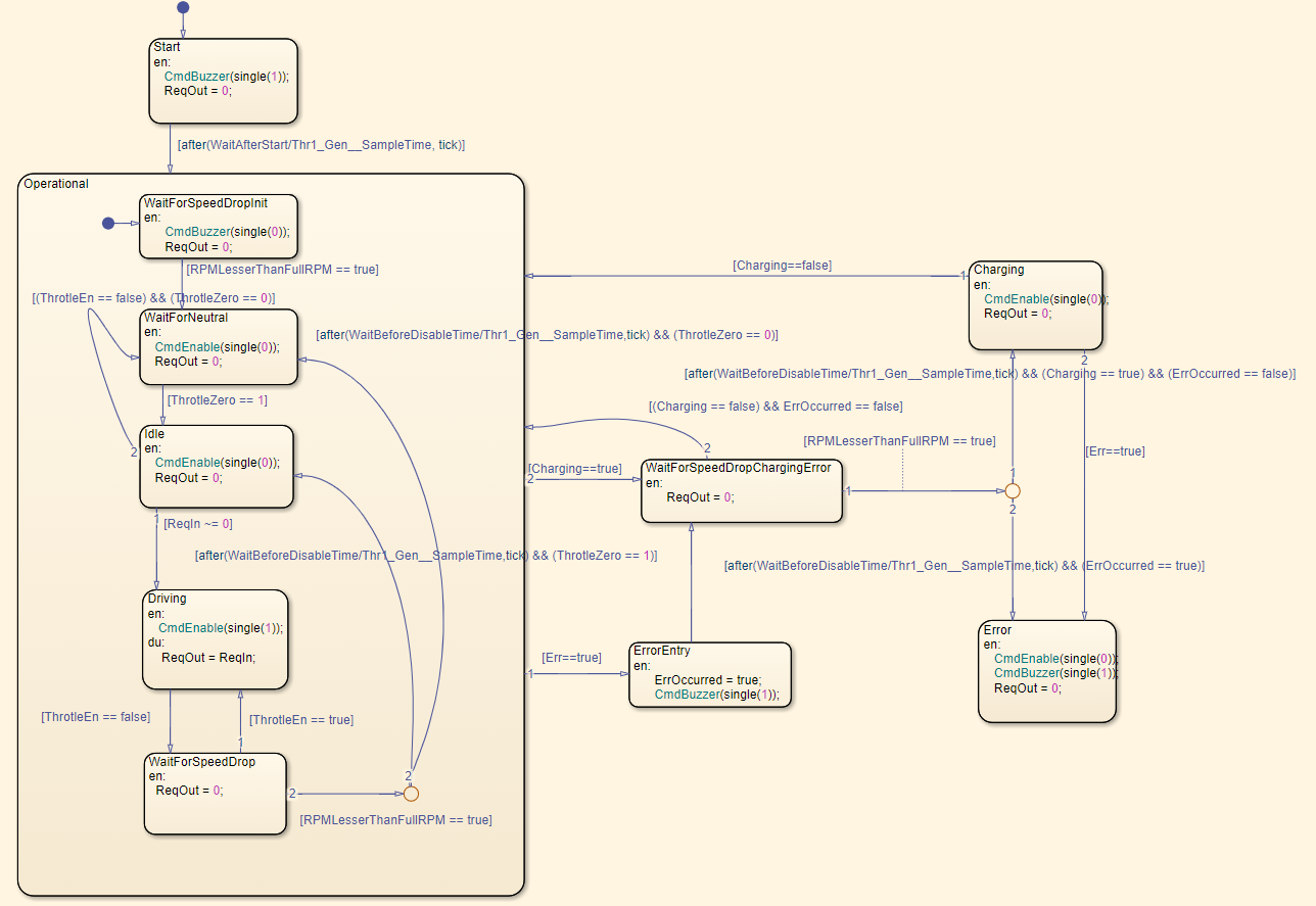
Startup State
- Buzzer Activation: Upon system start, the buzzer is activated if an external buzzer is connected.
- Wait Time: The system waits for the duration specified by the parameter Thr1_Throttle__WaitAfterStart to complete the startup.
- Error Check: If an error is detected during startup, the system transitions directly to the Error State.
Operational State
- Buzzer Deactivation: The buzzer is disabled upon entering the operational state.
- RPM Check: The system waits for the RPM to drop to 0, if it is not already there.
- Bridge Disable: The bridge is disabled, and the system waits for the throttle to be set to zero.
Idle State
- Idle Mode: The system enters the Idle State, waiting for the input to move out of the zero position.
Driving State
- Throttle Enabled: If the input moves out of the zero position and the throttle is enabled, the system transitions to the Driving State.
- Bridge Enable: The bridge is enabled, and the output is forwarded to motor control.
WaitForNeutral State
- Throttle Disabled: If the throttle is disabled and the output moves out of the zero position, the system returns to the WaitForNeutral State.
WaitForSpeedDrop State
- Output Set to 0: When the throttle is disabled during the Driving State (either due to Thr1_Enable__Throttle being set to 0, input within the disable dead band, or outside allowed values), the system enters the WaitForSpeedDrop State.
- RPM Check: The output is set to 0, but the bridge remains enabled until the RPM drops below the value specified by Thr1_Brake__Full_RPM.
- Wait Time: The system waits for the time configured in Thr1_Throttle__WaitBeforeBridgeDisable.
- State Transition: The state changes to Idle or WaitForNeutral based on whether the input is at zero or not.
Charging State
- RPM Drop: If charging is detected during the operational state, the system waits for the RPM to drop.
- Bridge Disable: The system moves to the Charging State, where the bridge is disabled.
- Return to Operational: When charging is no longer detected, the system returns to the operational state.
Error State
- Error Detection: If an error is detected in any state, the system transitions to the Error State.
- Bridge Disable: The bridge is disabled, and the buzzer is activated.
- RPM Check: In case of an error during the operational state, the system waits for the RPM to drop before disabling the bridge.
- Priority to Error State: If both charging and an error are detected simultaneously, the system prioritizes transitioning to the Error State.
- System Reset: There is no automatic recovery from the Error State; the system must be manually reset.
3.3.2 Input to Output Transformation
The input to output transformation converts the input voltage of the analog input to output torque, which is forwarded to motor control if the throttle is enabled. The basic transformation is illustrated in the graph below.

- Thr1_Throttle__ZeroValue: Defines the zero point of the input.
- Thr1_Throttle__ZeroDeadBand: Defines the dead band around the zero point. While the input voltage is within this dead band, the output remains zero.
- Thr1_Throttle__MinInput: Minimum valid input voltage.
- Thr1_Throttle__MaxInput: Maximum valid input voltage.
- Thr1_Throttle__OutFullPositive: Maximum positive output torque.
- Thr1_Throttle__OutFullNegative: Maximum negative output torque.
- Thr1_Throttle__NonValidMin: Minimum input voltage considered valid.
- Thr1_Throttle__NonValidMax: Maximum input voltage considered valid.
The transformation includes the following regions:
-
Zero Dead Band:
- Defined by
Thr1_Throttle__ZeroValueandThr1_Throttle__ZeroDeadBand. - Output remains zero when input voltage is within the dead band.
- Defined by
-
Positive Throttle Region:
- From the end of the dead band to
Thr1_Throttle__MaxInput, the output rises in the positive direction from 0 toThr1_Throttle__OutFullPositive. - Output is calculated as , where is the normalized output (0 at 0 and 1 at
Thr1_Throttle__OutFullPositive), is the normalized input (0 at the edge of the dead band and 1 atThr1_Throttle__MaxInput), and is the parameterThr1_Throttle__Progressive, which ranges between 0.3 and 3. The default value for is 1, indicating a linear growth of output torque.
- From the end of the dead band to
-
Negative Throttle Region:
- From the end of the dead band to
Thr1_Throttle__MinInput, the output falls in the negative direction. - Output is calculated as y=−∣x∣a
- From the end of the dead band to
-
Constant Max Throttle Region:
- Between
Thr1_Throttle__MaxInputandThr1_Throttle__NonValidMax, the output remains at maximum positive torque. - Between
Thr1_Throttle__MinInputandThr1_Throttle__NonValidMin, the output remains at maximum negative torque. - If the input value increases beyond
Thr1_Throttle__NonValidMaxor decreases beyondThr1_Throttle__NonValidMin, the output torque is set to 0 and the throttle module enters the error state.
- Between
This transformation ensures that the throttle application accurately converts the input voltage into the appropriate output for motor control, with safeguards in place to handle invalid input values and prevent unintended behaviour.
3.3.2.1 Progressive
The following chart illustrates how the throttle output changes based on different values of the Thr1_Throttle__Progressive parameter. This parameter modifies the response curve of the throttle, allowing for either a more gradual or more aggressive acceleration profile.
- Black Curve: Represents a linear throttle response where
Thr1_Throttle__Progressiveis set to 1. In this case, the output increases proportionally to the input. - Red Curve: Shows a concave transformation where
Thr1_Throttle__Progressiveis set to a value between 0.3 and 1. This setting results in a more responsive output at low throttle inputs, making the vehicle more reactive to small changes in input. - Blue Curve: Represents a convex transformation where
Thr1_Throttle__Progressiveis set to a value between 1 and 3. This setting provides a smoother and less sensitive response at lower inputs, allowing for finer control before reaching full throttle.
Understanding the Impact of Progressive Values
- When
Thr1_Throttle__Progressive< 1, the initial throttle response is stronger, and the output rises quickly at lower input values. - When
Thr1_Throttle__Progressive= 1, the response remains linear. - When
Thr1_Throttle__Progressive> 1, the output starts increasing more gradually, providing finer control in the lower range.
By adjusting this parameter, the response can be fine-tuned so that the throttle behaviour matches specific application needs.

3.3.3 Other throttle module functions
Enable dead band
Enable Dead Band functions similarly to Zero Dead Band. However, instead of setting the throttle output to 0, it disables the driver bridge when the input is less than a specified distance from the zero point. This distance is determined by the Enable Dead Band threshold. To disable Enable Dead Band, set its value to 0.
Ensure this threshold is always smaller than the Zero Dead Band threshold to prevent unusual behaviour.
Disable at brake
When the parameter 0x4013 0x0E DissableAtBrake is set to 1, the throttle module output is set to zero whenever the brake is active. This means that as soon as the brake is applied, the emDrive system will start braking immediately, regardless of the throttle input.
When the parameter 0x4013 0x0E DissableAtBrake is set to 0, the throttle and brake outputs are combined before being sent to motor control. In this case, the emDrive system will only start braking if the brake output is greater than the throttle output.
Rate limit
The rate limit controls how quickly the output can change in response to changes in the input (Higher the number, faster the change). This is determined by the parameter 0x4013 0x0A RateLimit.
When the input changes from 0 to 1 (works on normed value), the output will change from 0 to 1 in 1 / RateLimit seconds.
Output of throttle at zero value
If the application needs a specific output (not zero) to be set at zero position of a potentiometer 0x4013 0x01 ZeroValue, the object 0x4013 0x0D OutStartPositive can be set to achieve this functionality. This will be presented in Throttle example 4.
With this feature the 0x4013 - Thr1_Throttle__EnableDeadBand, should be disabled

3.3.4 Examples
- Throttle example 1
Description:
Monodirectional throttle using only one analog input.
In this example, we will use a potentiometer as our throttle input. Our goal is to control the motor in velocity mode, ranging from 0 to 100 RPM.
Throttle Input Details
Potentiometer: Used as the throttle input. Connected to AIN3 = 0x3090 0x03
Voltage and RPM Control
Error Condition: If the voltage from the potentiometer is lower than 0.2V or higher than 4.8V, an error will occur (indicating a possible short or broken connection).
0 RPM: At 0.5V, the motor should run at 0 RPM.
100 RPM: At 4.5V, the motor should run at the maximum speed of 100 RPM.
Objects to set:
-
- Enable Throttle Application:
0x4010 0x01 - Thr1_Gen__Enable = 1 - Enable the Throttle Module:
Use the throttle general object0x4011 Thr1_Enableto enable the proper module.0x4011 0x01 Throttle = 1 - Map Objects to the Application:
Choose the reference value to control (velocity or torque) and map analog/digital inputs and outputs.
To control velocity:0x4012 0x06 TargetObj = 0x301005
To control torque:0x4012 0x06 TargetObj = 0x301004
Set the control mode (0 for torque, 1 for velocity):0x3100 0x01 ControlMode = 0 or 1
Define the analog throttle input (potentiometer on AIN3):0x4012 0x03 ThrottleInput = 0x309003 - Configure the Throttle Module:
Set the throttle voltage parameters as explained in Section 4.2:0x4013 0x01 ZeroValue = 0.50x4013 0x04 MaxInput = 4.50x4013 0x05 MinInput = 0.50x4013 0x06 NonValidMax = 4.80x4013 0x07 NonValidMin = 0.2
Set the maximum and minimum TorqueRef or VelocityRef:
In this example we will use max = 100rpm and min = 0rpm0x4013 0x0B OutFullPositive = 1000x4013 0x0C OutFullNegative = 0 - Save and Reset:
Save the settings (Ctrl+S) and perform a reset.
Switch to operational mode.
Test
Enable auto start if everything works correctly (inverter will always go to operational mode after reset).0x3000 0x03 AutoStart = 1
- Enable Throttle Application:
- Throttle example 2
Description:
In this example, we will use the same potentiometer as in Throttle Example 1. The main difference is that this setup allows for bidirectional control of the throttle. Here’s how it works:
- At 2.5V, the motor will be at 0 RPM.
- At 4.5V, the motor will run at 100 RPM.
- At 0.5V, the motor will run at -100 RPM (in reverse).
This setup enables you to control the motor speed and direction using a single analog input.
Objects to set:
-
- Same as example "Throttle example 1"
- Same as example "Throttle example 1"
- Same as example "Throttle example 1"
- Configure the Throttle Module:
Set the throttle voltage parameters as explained in Section 4.2:0x4013 0x01 ZeroValue = 2.50x4013 0x04 MaxInput = 4.50x4013 0x05 MinInput = 0.50x4013 0x06 NonValidMax = 4.80x4013 0x07 NonValidMin = 0.2
Set the maximum and minimum TorqueRef or VelocityRef:
In this example we will use max = 100rpm and min = -100rpm0x4013 0x0B OutFullPositive = 1000x4013 0x0C OutFullNegative = -100
Additionaly we have to setIsNegativeBrake0x4013 0x11 IsNegativeBrake = 0 - Same as example "Throttle example 1"
- Throttle example 3
Description:
In this example, we will use the same potentiometer as in Throttle Example 1, along with two additional digital inputs to control the motor's direction.
Digital input 1 = 0x30B0 0x01 DIN1 - enable/disable positive throttle
Digital input 2 = 0x30B0 0x02 DIN2 - enable/disable negative throttle.
Objects to set:
-
- Same as example "Throttle example 1"
- Same as example "Throttle example 1"
- Same as example "Throttle example 1"
- Same as example "Throttle example 1"
Additionally, we only need to map digital input objects for enabling forward/reverse throttle.
e.g.
We will use object0x30B0 0x01 - DIN1to enable/disable positive throttle.
We will use object0x30B0 0x02 - DIN2to enable/disable negative throttle.
So we need to set:0x4012 0x04 ThrottleFWD_Dlvalue = 0x30b0010x4012 0x05 ThrottleREW_Dlvalue = 0x30b002
If DIN1 and DIN2 are the same value, the throttle will not work. Only one of them can be 1 and the other 0.
Currently the inverter does not support using only one physical input (e.g switch) to change direction. There must be two of them!
Additionaly we have to setIsNegativeBrake0x4013 0x11 IsNegativeBrake = 0 - Same as example "Throttle example 1"
- Throttle example 4
Description:
In this example, we will need a working "Throttle example 1", the main difference will be that at 0.5V we want 100RPM and then we want to ramp up do the max value of 200 RPM.
We also want to have an ignition switch (enable switch). Which will be connected to 0x30B0 0x01 - DIN1
We need to set the OutFullPositive = MAX desired RPM
We need to set the OutStartPositive = Standby RPMs
0x4013 0x0B - OutFullPositive = 1000x4013 0x0D - OutStartPositive = 100
With these settings you can try the application, where you will see that you can never disable the motor. If you go to the min position of the potentiometer the motor will spin with 100 RPM.
Setting the switch:
Currently there is a workaround to have an ignition switch which will be changed in the future official release.
To get the ignition switch working we need to map the 0x30B0 0x01 - DIN1 to ThrottleFWD_Dlvalue
0x4012 0x04 - ThrottleFWD_Dlvalue = 0x30B0010x4012 0x05 - ThrottleREW_Dlvalue = 0x302001 This is the workaround we map the 0x3020 0x01 - gen1_8bit to the throttle application. This value shall be always at default = 0.
If the throttle potentiometer is in any position other than at 0 e.g. at motor spins at 140RPM and you disable the ignition switch, the motor will stop spinning. But if you then start ignition again it will go directly to the rpm that are set with throttle (in this example back to 140RPM). You need to put the throttle to min.
With this workaround only monodirectional throttle + ignition will work. In the future FW release, there will be a new object for ignition/enable and it will work also in bidirectional throttle.
The protection will also be implemented so that it does not spin out of control.
- Throttle example 5
Description:
Monodirectional throttle that uses a single analog input and provides gradual braking when the throttle is released.
In this example, a potentiometer is used as the throttle input. The goal is to control the motor in torque mode, with a torque range from 0 to 10 Nm. Additionally, we want to simulate the behaviour of a combustion engine. This means that when the throttle pedal is released (i.e. the potentiometer goes to its lowest setting), the system does not coast but instead applies braking (engine braking). This effect is achieved using only the throttle module.
Throttle Input Details
Potentiometer: Used as the throttle input. Connected to AIN3 = 0x3090 0x03
Voltage and RPM Control
Error Condition: If the voltage from the potentiometer is lower than 0.2V or higher than 4.8V, an error will occur (indicating a possible short or broken connection).
0 Nm: At 1V
10 Nm: At 4.5V, the motor should run at the maximum torque of 10 Nm
-5 Nm: At 0.5V, the motor should brake with maximum torque of 5 Nm - With the decrease of the RPMs the braking torque is also steadily decreased.
Objects to set:
-
- Enable Throttle Application:
0x4010 0x01 - Thr1_Gen__Enable = 1 - Enable the Throttle Module:
Use the throttle general object0x4011 Thr1_Enableto enable the proper module.0x4011 0x01 Throttle = 1 - Map Objects to the Application:
Choose the reference value to control (velocity or torque) and map analog/digital inputs and outputs.
To control torque:0x4012 0x06 TargetObj = 0x301004
Set the control mode (0 for torque, 1 for velocity):0x3100 0x01 ControlMode = 0
Define the analog throttle input (potentiometer on AIN3):0x4012 0x03 ThrottleInput = 0x309003 - Configure the Throttle Module:
Set the throttle voltage parameters as explained in Section 4.2:0x4013 0x01 ZeroValue = 10x4013 0x04 MaxInput = 4.50x4013 0x05 MinInput = 10x4013 0x06 NonValidMax = 4.80x4013 0x07 NonValidMin = 0.2
Set the maximum and minimum TorqueRef or VelocityRef:
In this example we will use max = 10Nm and min = -5Nm0x4013 0x0B OutFullPositive = 100x4013 0x0C OutFullNegative = -5
Set the setting saying that negative throttle will be treated as brake0x4013 0x11 IsNegativeBrake = 1 - Save and Reset:
Save the settings (Ctrl+S) and perform a reset.
Switch to operational mode.
Test
Enable auto start if everything works correctly (inverter will always go to operational mode after reset).0x3000 0x03 AutoStart = 1
- Enable Throttle Application:
3.4. Brake module
The brake module implements the brake function within the throttle application, operating similarly to the throttle module but with a crucial difference: it always outputs torque in the opposite direction of the current rotation and supports only monodirectional braking. The brake can be assigned to a different analog input or share the same analog input as the throttle module, beneficial for configurations where monodirectional throttle is used. In such cases, one direction from the zero point can manage throttle control while the other handles brake control.
The brake module is used only when the inverter is operating in torque mode. In velocity mode, it is unnecessary because the velocity control system manages deceleration. For example, when operating at 3000 RPM, the velocity control system will handle the transition to 0 RPM. However, in torque mode, if you apply 10 Nm and then reduce the torque to 0 Nm, the motor will coast rather than braking in a controlled manner.
| Object Name |
Object Index |
Object Subindex |
Description | Unit |
| Thr1_Brake__ZeroValue | 0x4014 | 0x01 | At this input value output is zero. | V |
| Thr1_Brake__ZeroDeadBand | 0x4014 | 0x02 | Defines how large zero dead band is | V |
| Thr1_Brake__EnableDeadBand | 0x4014 | 0x03 | Defines how large enable dead band is. Should be lesser or equal to zero dead band. |
V |
| Thr1_Brake__MaxInput | 0x4014 | 0x04 | At this input value output is at maximum value |
V |
| Thr1_Brake__NonValidMax | 0x4014 | 0x05 | Any input value grater then this will put throttle module into error state. |
V |
| Thr1_Brake__NonValidMin | 0x4014 | 0x06 | Any input value lesser than this will put throttle module into error state. |
V |
| Thr1_Brake__Progressive | 0x4014 | 0x07 | At values > 1 brake will be progressive (it will slowly rise output value at beginning and then sharply on the end). For values < 1 it is exactly opposite - sharply increase at beginning and then slow increase at end. Mathematical at normed value (0-1) out = power(in, progressive) | / |
| Thr1_Brake__RateLimit | 0x4014 | 0x08 | Limits how fast output can change. Output can change from 0 to 1 in 1/Thr1_Brake__RateLimit s |
1/s |
| Thr1_Brake__OutFull | 0x4014 | 0x09 | Output brake torque when input reaches max input. |
/ |
| Thr1_Brake__OutZero | 0x4014 | 0x0A | Output brake torque when input is at zero point. |
/ |
| Thr1_Brake__Full_RPM | 0x4014 | 0x0B | Between 0 RPM and the value set by this parameter, the braking torque is gradually increased from 0% to 100%. Once the speed exceeds this value, full braking torque is applied. This approach helps prevent excessive braking torque at 0 RPM, especially if the speed signal is noisy. | / |
| Object Name |
Object Index |
Object Subindex |
Description | Unit |
| Thr1_Brake__Input | 0x4014 | 0x0C | Input signal | V |
| Thr1_Brake__OutNorm | 0x4014 | 0x0D | Normed brake output (-1 full negative, 1 full positive) |
/ |
| Thr1_Brake__Out | 0x4014 | 0x0E | Output in system units | / |
| Thr1_Brake__Enabled | 0x4014 | 0x0F | If Brake is out of centre position for EnableDeadBand - power stage enabled | Bit |
| Thr1_Brake__Err | 0x4014 | 0x10 | If brake input is outside NonValidMax and NonValidMin |
3.4.1 Input to Output Transformation
The input-to-output transformation operates similarly to the throttle module's input-output transformation. A typical example of this process is illustrated in the picture below.

The slope between the end of the zero-dead-band and Thr1_Brake__MaxInput is defined by the parameter Thr1_Brake__Progressive, similar to the throttle module. Additionally, you can configure the brake module to increase brake torque as the input decreases by setting Thr1_Brake__MaxInput to a value lower than Thr1_Brake__ZeroValue. This setup is especially useful for one-pedal driving, where the same potentiometer controls both braking and throttle. At lower input values, the system applies braking, while at higher values, it functions as a throttle. When operating in throttle mode, no braking is applied; when the pedal is completely released, the system enters braking mode. The resulting input-to-output transformation for this configuration is shown in the picture below

For both modes, it is essential to configure the parameters Thr1_Brake__NonValidMax and Thr1_Brake__NonValidMin. Failing to do so will result in incorrect operation of the short to ground and short to power supply error detection.
3.4.2 Examples
To use the brake module, you first need to configure the throttle module and ensure it works as expected.
- Brake example 1
Description:
Monodirectional throttle & brake using only one analog input.
In this example, a potentiometer is used to adjust voltage from 0V to 5V. The operational range is 0.2V to 4.8V. If the voltage goes outside this range, an error occurs.
Throttle and Brake Operation
Neutral Position: At 2.5V, the motor is in neutral.
Increasing Voltage: Raising the voltage above 2.5V speeds up the motor.
Decreasing Voltage: Lowering the voltage below 2.5V brakes the motor.
Before proceeding with this example, ensure you have completed and prepared a working setup of "Throttle Example 1" with torque control, not velocity. To achieve this, configure the following settings:
- Set Target Object:
0x4012 0x06 TargetObj = 0x301004 - Set Control Mode:
0x3100 0x01 ControlMode = 0
Objects to set:
- Enable Throttle Application:
0x4010 0x01 - Thr1_Gen__Enable = 1 - Enable the Throttle & Brake Module:
0x4011 0x01 Throttle = 10x4011 0x02 Brake = 1 - Map Objects to the Application:
Torque control0x4012 0x06 TargetObj = 0x301004
Check that torque mode is active if not set it with control mode = 0:0x3100 0x01 ControlMode = 0
Define the analog throttle input (e.g., potentiometer on AIN3):0x4012 0x03 ThrottleInput = 0x309003
Define the analog brake input (same as ThrottleInput in this example):0x4012 0x12 BrakeInput = 0x309003 - Configure the Throttle Module:
Set the throttle voltage parameters as explained in Section 4.2:0x4013 0x01 ZeroValue = 2.50x4013 0x04 MaxInput = 4.50x4013 0x05 MinInput = 0.50x4013 0x06 NonValidMax = 4.80x4013 0x07 NonValidMin = 0.2
Set the maximum and minimum TorqueRef
In this example we will use max = 10Nm and min = 0Nm (if there is no load) - BIDIRECTIONAL throttle must be dissabled (one of these must be 0) for using only one analog input as throttle and brake.0x4013 0x0B OutFullPositive = 100x4013 0x0C OutFullNegative = 0 - Configure the Brake Module:
Set the brake voltage parameters:0x4014 0x01 ZeroValue = 2.50x4014 0x04 MaxInput = 0.50x4014 0x05 NonValidMax = 4.80x4014 0x06 NonValidMin = 0.20x4014 0x09 OutFullPositive = 10 - Save and Reset:
Save the settings (Ctrl+S) and perform a reset.
Switch to operational mode.
Test
Enable auto start if everything works correctly (inverter will always go to operational mode after reset).0x3000 0x03 AutoStart = 1
- Brake example 2
Description:
In this example, we will use two analog inputs to control the motor:
- Analog Input 3: Controls the throttle (motor speed).
- Analog Input 2: Controls the brake.
This setup allows you to manage both the acceleration and deceleration of the motor independently using separate analog inputs.
Objects to set:
- Same as "Brake example 1"
- Same as "Brake example 1"
- Map Objects to the Application:
Torque control0x4012 0x06 TargetObj = 0x301004
Check that torque mode is active if not set it with control mode = 0:0x3100 0x01 ControlMode = 0
Define the analog throttle input (e.g., potentiometer on AIN3):0x4012 0x03 ThrottleInput = 0x309003
Define the analog brake input (e.g., potentiometer AIN2):0x4012 0x12 BrakeInput = 0x309002 - Configure the Throttle Module:
Set the throttle voltage parameters as explained in Section 4.2:0x4013 0x01 ZeroValue = 0.50x4013 0x04 MaxInput = 4.50x4013 0x05 MinInput = 0.50x4013 0x06 NonValidMax = 4.80x4013 0x07 NonValidMin = 0.2
Set the maximum and minimum TorqueRef
In this example we will use max = 10Nm and min = 0Nm0x4013 0x05 OutFullPositive = 100x4013 0x05 OutFullNegative = 0 - Configure the Brake Module:
Set the brake voltage parameters:0x4014 0x01 ZeroValue = 0.50x4014 0x04 MaxInput = 4.50x4014 0x05 NonValidMax = 4.80x4014 0x06 NonValidMin = 0.20x4014 0x09 OutFull = 10 - Save and Reset:
Save the settings (Ctrl+S) and perform a reset.
Switch to operational mode.
Test
Enable auto start if everything works correctly (inverter will always go to operational mode after reset).0x3000 0x03 AutoStart = 1
- Brake example 3
Description:
Monodirectional throttle & brake using one digital input (when connected full braking applied)
In this example, a potentiometer is used to adjust voltage from 0V to 5V. The operational range is 0.2V to 4.8V. If the voltage goes outside this range, an error occurs.
In this example, we will use one analog input and one digital input
- Analog Input 3: Controls the throttle
- Digital Input1: Controls the brake and disables the throttle.
Throttle and Brake Operation
Neutral Position: At 0.5V, the motor is in neutral .
Increasing Voltage: Raising the voltage above 0.5V speeds up the motor to max torque of 10Nm.
If brake input is activated throttle is disabled and full braking is applied.
Before proceeding with this example, ensure you have completed and prepared a working setup of "Throttle Example 1" with torque control, not velocity. To achieve this, configure the following settings:
- Set Target Object:
0x4012 0x06 TargetObj = 0x301004 - Set Control Mode:
0x3100 0x01 ControlMode = 0
Objects to set:
- Enable Throttle Application:
0x4010 0x01 - Thr1_Gen__Enable = 1 - Enable the Throttle & Brake Module:
0x4011 0x01 Throttle = 10x4011 0x02 Brake = 1 - Map Objects to the Application:
Torque control0x4012 0x06 TargetObj = 0x301004
Check that torque mode is active if not set it with control mode = 0:0x3100 0x01 ControlMode = 0
Define the analog throttle input (e.g., potentiometer on AIN3):0x4012 0x03 ThrottleInput = 0x309003
Define the analog brake input (e.g. DIN1 at object 0x30B0 0x01):0x4012 0x12 BrakeInput = 0x0x30B001 - Configure the Throttle Module:
Set the throttle voltage parameters as explained in Section 4.2:0x4013 0x01 ZeroValue = 0.50x4013 0x04 MaxInput = 4.50x4013 0x05 MinInput = 0.50x4013 0x06 NonValidMax = 4.80x4013 0x07 NonValidMin = 0.2
Set the maximum and minimum TorqueRef
In this example we will use max = 10Nm and min = 0Nm.0x4013 0x0B OutFullPositive = 100x4013 0x0C OutFullNegative = 0
Dissable throttle when brake is applied0x4013 0x0E DisableAtBrake = 1 - Configure the Brake Module:
Set the brake voltage parameters:
We need to dissable the out of bounds funcitonalites as the digital input has only 2 values 0 and 1.0x4014 0x01 ZeroValue = 00x4014 0x04 MaxInput = 10x4014 0x05 NonValidMax = 4.80x4014 0x06 NonValidMin = -20x4014 0x09 OutFull = 10 - Save and Reset:
Save the settings (Ctrl+S) and perform a reset.
Switch to operational mode.
Test
Enable auto start if everything works correctly (inverter will always go to operational mode after reset).0x3000 0x03 AutoStart = 1
3.5. Pump control module
The Pump Control Module manages the operation of two pumps in the system: the Pump1 = main pump and the Pump2 = cooling pump.
The Pump1 (main pump) is activated whenever
- The throttle application is in the run state,
- The cooling pump is active, or
- The temperature exceeds the set value (
Thr1_Pump__1OnTemperature).
The Pump2 (cooling pump) is regulated by a simple hysteresis controller. There are two options for activating the Pump2 (cooling pump):
If both Thr1_Pump__2OnTemperature and Thr1_Pump__2OffTemperatureare set to -40 °C, the controller uses the values of Thr1_Pump__1OnTemperature and Thr1_Pump__1OffTemperature. Otherwise, it uses the directly configured values of Thr1_Pump__2OnTemperatureand Thr1_Pump__2OffTemperature.
Following example if Thr1_Pump__2OnTemperature = -40 and Thr1_Pump__2OffTemperature = -40

| Object Name |
Object Index |
Object Subindex |
Description | Unit |
| Thr1_Pump__1OnTemperature | 0x4015 | 0x01 | At which temperature cooling pump1 will be enabled | °C |
| Thr1_Pump__1OFFTemperature | 0x4015 | 0x02 | At which temperature cooling pump1 will be disabled. Must be lower as Thr1_Pump__Pump1OnTemperature |
°C |
| Thr1_Pump__2OnTemperature | 0x4015 | 0x03 | At which temperature cooling pump2 will be enabled. If -40, Pump 1thresold will be used for pump 2. |
°C |
| Thr1_Pump__2OFFTemperature | 0x4015 | 0x04 | At which temperature cooling pump2 will be disabled. Must be lower as Thr1_Pump__Pump2OnTemperature. If -40, Pump1 threshold will be used. |
°C |
| Object Name |
Object Index |
Object Subindex |
Description | Unit |
| Thr1_Pump__Pump1TemperatureIn | 0x4015 | 0x05 | Main pump input temperature | °C |
| Thr1_Pump__Pump2TemperatureIn | 0x4015 | 0x06 | Cooling pump input temperature | °C |
3.5.3 Examples
- Pump example 1
Description
Main pump on LS3 0x30A2 0x02 Value
Cooling pump on LS4 0x30A3 0x02 Value
When PWMs are enabled, the main pump is always ON regardless of the input temperatures.
Both Pump1TemperatureIn and Pump2TemperatureIn are used. When PWMs are disabled, if either value exceeds the setting in Thr1_Pump__1OnTemperature , both pumps turn ON. They turn OFF only when both values fall below Thr1_Pump__1OffTemperature. When PWMs are enabled main pump is ON and the logic for cooling pump behaviour is not changed.
Temperature at which we start the pumps = 60 °C
Temperature at which we stop the pumps = 50 °C
Objects to set:
- Enable Throttle Application:
0x4010 0x01 - Thr1_Gen_Enable = 1 - Enable the Pump Module:
0x4011 0x03 Pump = 1 - Map Objects to the Application:
For this module theCoolingInputTemperature1andCoolingInputTemperature2are set by default.Ctrl_Bridge__StatusHeatsinkTempis mapped toCoolingInputTemperature1Ctrl_Gen_Stat__MotorSensorTempis mapped toCoolingInputTemperature20x4012 0x0D CoolingInputTemperature1 = 0x31CE000x4012 0x0E CoolingInputTemperature2 = 0x31010A
Next we need to map the digital outputs where our pumps are connected to. In this example we will use:
Main pump on LS30x30A2 0x02 Value
Cooling pump on LS40x30A3 0x02 Value0x4012 0x0B Pump1EnableDO = 0x30A2020x4012 0x0C Pump2EnableDO = 0x30A302 - Configure the Pump Module:
Set the temperature at which the pump starts and stops.0x4015 0x01 Pump1OnTemperature = 600x4015 0x02 Pump1OffTemperature = 50 - Save and Reset:
Save the settings (Ctrl+S) and perform a reset.
Switch to operational mode.
Test
Enable auto start if everything works correctly (inverter will always go to operational mode after reset).0x3000 0x03 AutoStart = 1
- Pump example 2
Description
Main pump on LS3 0x30A2 0x02 Value
Cooling pump on LS4 0x30A3 0x02 Value
With this example we use separate temperature thresholds for each pump. the logic is the same as in example 1 the only difference is now that each pump has its own hysteresis when to turn on and off.
When PWMs are enabled, the main pump is always ON regardless of the input temperatures.
Temperature at which we start the main pump = 60 °C
Temperature at which we stop the main pump = 50 °C
Temperature at which we start the cooling pump = 80 °C
Temperature at which we stop the cooling pump = 70 °C
Objects to set:
- Enable Throttle Application:
0x4010 0x01 - Thr1_Gen_Enable = 1 - Enable the Pump Module:
0x4011 0x03 Pump = 1 - Map Objects to the Application:
For this module theCoolingInputTemperature1andCoolingInputTemperature2are set by default.Ctrl_Bridge__StatusHeatsinkTempis mapped toCoolingInputTemperature1Ctrl_Gen_Stat__MotorSensorTempis mapped toCoolingInputTemperature20x4012 0x0D CoolingInputTemperature1 = 0x31CE000x4012 0x0E CoolingInputTemperature2 = 0x31010A
Next we need to map the digital outputs where our pumps are connected to. In this example we will use:
Main pump on LS30x30A2 0x02 Value
Cooling pump on LS40x30A3 0x02 Value0x4012 0x0B Pump1EnableDO = 0x30A2020x4012 0x0C Pump2EnableDO = 0x30A302 - Configure the Pump Module:
Set the temperature at which the pump starts and stops.0x4015 0x01 Pump1OnTemperature = 600x4015 0x02 Pump1OffTemperature = 500x4015 0x01 Pump1OnTemperature = 800x4015 0x02 Pump1OffTemperature = 70
- Save and Reset:
Save the settings (Ctrl+S) and perform a reset.
Switch to operational mode.
Test
Enable auto start if everything works correctly (inverter will always go to operational mode after reset).0x3000 0x03 AutoStart = 1
3.6. DC-DC turn on delay module
DC-DC turn on delay module enables an external DC-DC module with a delay after start-up. The delay time
can be configured by setting parameter Thr1_DCDC__StartupDelay
| Object Name |
Object Index |
Object Subindex |
Description | Unit |
| Thr1_DCDC__StartupDelay | 0x4017 | 0x00 | Delay time after which external DC-DC module is turned on | s |
3.6.1 Examples
- DC-DC delay example 1
The relay is connected to LS2 0x30A1 0x02 Value
DC-DC turn on delay set to 5s.
Objects to set:
- Enable Throttle Application:
0x4010 0x01 - Thr1_Gen_Enable = 1 - Enable the DC-DC Module:
0x4011 0x05 DC_DC = 1 - Map Objects to the Application:
DC-DC relay is on LS20x30A1 0x02 Value0x4012 0x0F DCDCenableDO = 0x30A102 - Configure the DC-DC Module:
Set the delay to 5s0x4017 0x00 Thr1_DCDC__StartupDelay = 5 - Save and Reset:
Save the settings (Ctrl+S) and perform a reset.
Switch to operational mode.
Test
Enable auto start if everything works correctly (inverter will always go to operational mode after reset).0x3000 0x03 AutoStart = 1
3.7. SOC monitoring and charging detection module
The SOC (State of Charge) monitoring module and the charging detection module are implemented together due to their similarities. However, both modules can be enabled and disabled independently. SOC monitoring requires a Battery Management System (BMS) to detect SOC. Note that the BMS is not included in the emDrive. If SOC monitoring is needed, an independent BMS must be connected to the CAN bus.
| Object Name |
Object Index |
Object Subindex |
Description | Unit |
| Thr1_Bat__StartLimitingSOC | 0x4018 | 0x01 | SOC percentage at which throttle limiting starts. | % |
| Thr1_Bat__EndLimitingSOC | 0x4018 | 0x02 | SOC percentage at which throttle limiting is at maximum |
% |
| Thr1_Bat__EndLimitingThrottleOut | 0x4018 | 0x03 | Maximum torque output when throttle limiting is at maximum. |
/ |
| Thr1_Bat__ThrottleLimitRamp | 0x4018 | 0x04 | Limits how fast throttle limiting can change. | 1/s |
| Object Name |
Object Index |
Object Subindex |
Description | Unit |
| Thr1_Bat__Valid | 0x4018 | 0x05 | If 0, no BMS is available | / |
| Thr1_Bat__SOC | 0x4018 | 0x06 | Battery SOC in percentage | % |
| Thr1_Bat__LimitThrottle | 0x4018 | 0x07 | Current throttle limit in system units | / |
| Thr1_Bat__LimitNorm | 0x4018 | 0x08 | Normed current throttle limit. (1 -> no limiting, 0 -> maximum allowed limit) |
/ |
| Thr1_Bat__Charging | 0x4018 | 0x09 | If 1, charging is detected. If 0 charging is not detected. |
Bit |
3.7.1 SOC Monitoring Module
The SOC monitoring module tracks the SOC state as reported by the BMS.
-
Behaviour:
- If SOC drops below the level specified by the parameter
Thr1_Bat__StartLimitingSOC, the module will start limiting the maximum output. - If SOC falls below the level specified by
Thr1_Bat__EndLimitingSOC, the maximum output will be set to the value given inThr1_Bat__EndLimitingThrottleOut. - When SOC is between
Thr1_Bat__StartLimitingSOCandThr1_Bat__EndLimitingSOC, the maximum output is linearly reduced. The reduction goes from the maximum output (as defined in the throttle module) atThr1_Bat__StartLimitingSOCto the output defined inThr1_Bat__EndLimitingThrottleOutatThr1_Bat__EndLimitingSOC.

- If SOC drops below the level specified by the parameter
-
Throttle Limiting Speed:
- Controlled by the parameter
Thr1_Bat__ThrottleLimitRamp. - The limiting speed functions similarly to rate limiting in the throttle and brake modules, where throttle limiting can range from 0 to 1 in
1/Thr1_Bat__ThrottleLimitRampseconds.
- Controlled by the parameter
3.7.2 Charging detection Module
The charging detection module monitors whether the battery is being charged and reports this status to the throttle module.
- Behaviour::
- If a BMS is present, the module queries the BMS to check if the battery is currently being charged.
- Alternatively, the module can observe the state of the input mapped to the parameter
Thr1_Obj__ChargingDetectDIvalue:- If the value is 1, the battery is considered to be charging.
- If the value is 0, the battery is considered to be not charging.
This setup allows for accurate monitoring and management of the battery's state of charge and charging status, ensuring optimal performance and safety.
3.7.4 Examples
- SOC example 1
Description:
In this example we first need a working example of Throttle module to control torque. (It is also possible to control velocity.)
Next we need the following values:
- Battery (BMS) valid/present
- SOC in percent
To achieve this we can use the PDOs to get the values - in this example we will assume that we get the upper values via CAN and we set the values to our 0x2051 Customer_Data_16bit__Value. How to configure the PDOs refer to the user manual section 9.4-Data transfer – Process Data Object (PDO).
Battery (BMS) valid/present needs to be higher than 0, otherwise inverter thinks there is no BMS.
0x2051 0x01 Customer_Data_16bit__Value1 = Battery (BMS) valid/present (needs to be higher than 0)
0x2051 0x02 Customer_Data_16bit__Value2 = SOC in percent
We will start limiting the output when the battery has SOC = 10%
We will limit the output with a ramp of value 0.01 until we reach SOC = 5%, after which we stay at value 10Nm (in case of velocity control the unit of this value will be in PRM - 10RPM).
Objects to set:
-
- Enable the SOC Module:
Use the throttle general object0x4011 Thr1_Enableto enable the proper module.0x4011 0x06 SOC = 1 - Map Objects to the Application:
As mentioned above we have the required date on the Costomer_Data_16bit_Values.Customer_Data_16bit__Value1 = 0x2051 0x01Customer_Data_16bit__Value2 = 0x2051 0x02
We set the following:0x4012 0x07 BatValid = 0x2051010x4012 0x08 BatSOC = 0x205102
- Enable the SOC Module:
- Configure the SOC Module:
Set at what SOC percent we start limiting the output (at 10 %):0x4018 0x01 StartLimitingSOC = 10
Set at what SOC percent we stop limiting the output (at 5 %):0x4018 0x02 EndLimitingSOC = 5
Set what will the max value output be at the valueEndLimitingSOC(10Nm):0x4018 0x03 EndLimitingThrottleOut = 10
Set the ramp parameter for slope:0x4018 0x04 ThrottleLimitRamp = 0.01 - Save and Reset:
Save the settings (Ctrl+S) and perform a reset.
Switch to operational mode.
Test
Enable auto start if everything works correctly (inverter will always go to operational mode after reset).0x3000 0x03 AutoStart = 1
- Charging detection example 2
Description:
You need a working throttle example.
As mentioned above we can detect charging with the state that is reported by BMS for that we need to get the state of the BMS in this example we will use method as in SOC example 1, where use the PDOs and save the state to Costomer_Data_16bit_Value.Customer_Data_16bit__Value1 = 0x2051 0x01 = Battery (BMS) Valid/present (needs to be higher than 0)Customer_Data_16bit__Value3 = 0x2051 0x03 = State of BMS
Objects to set:
-
- Enable the SOCModule and ChargingDetect Module:
Use the throttle general object0x4011 Thr1_Enableto enable the proper module.0x4011 0x06 SOC = 10x4011 0x07 ChargingDetect = 1 - Map Objects to the Application:
As mentioned above we have the required date on the Costomer_Data_16bit_Values.Customer_Data_16bit__Value1 = 0x2051 0x01Customer_Data_16bit__Value3 = 0x2051 0x03
We set the following:0x4012 0x07 BatValid = 0x2051010x4012 0x09 BatState = 0x205103
- Enable the SOCModule and ChargingDetect Module:
- Configure the ChargingDetect Module:
With this module there is no other configuration needed. If the value onCustomer_Data_16bit__Value3== (charge = 4) or (charge_done = 5) -> driving is disabled. - Save and Reset:
Save the settings (Ctrl+S) and perform a reset.
Switch to operational mode.
Test
Enable auto start if everything works correctly (inverter will always go to operational mode after reset).0x3000 0x03 AutoStart = 1
- Charging detection example 3
Description:
You need a working throttle example.
The next method is to detect charging with a digital input, for that we will use digital input 4.
0x30B0 0x04 DIN4
Objects to set:
-
- Enable the SOCModule and ChargingDetect Module:
Use the throttle general object0x4011 Thr1_Enableto enable the proper module.0x4011 0x06 SOC = 10x4011 0x07 ChargingDetect = 1 - Map Objects to the Application:
As mentioned above we have the required date on the Costomer_Data_16bit_Values.Customer_Data_16bit__Value1 = 0x2051 0x01DIN4 = 0x30B0 0x04
We set the following:0x4012 0x07 BatValid = 0x2051010x4012 0x0A ChargingDetectDlvalue = 0x30B004
- Enable the SOCModule and ChargingDetect Module:
- Configure the ChargingDetect Module:
With this module there is no other configuration needed. If the value of DIN4 == 1 -> driving is disabled. - Save and Reset:
Save the settings (Ctrl+S) and perform a reset.
Switch to operational mode.
Test
Enable auto start if everything works correctly (inverter will always go to operational mode after reset).0x3000 0x03 AutoStart = 1
Interfacing To Inverter using Python and Peak CAN Interface
Emsiso Inverters primarily use the CANOpen protocol to communicate with outside tools. It is possible to use public libraries to communicate with the inverter using Python to automate production or assembly processes.
In this article, we will show how to connect to an Emsiso inverter using a PEAK CAN Interface and set/get a parameter value using an SDO Read/Write operations.
The library that we use in this guide is:
canopen-python/canopen: CANopen for Python
- Note that all conditions or limitations still remain the same as if using the emDrive Configurator.
- The article is intended for programmers with working knowledge of Python.
- This article expects a basic understanding of CANOpen. It is suggested to get a cursory overview by reading this article on CANOpen basics: CANopen Explained - A Simple Intro [2025] – CSS Electronics
We will be using the publicly available Python CANOpen Library: canopen · PyPI
Note that most of the documentation on this page is lifted from the referenced pages, with minor modifications in order to show interfacing to the inverter.
Exhaustive documentation for canopen is available on the official docu website:
canopen 0.1.dev52+ge840449 documentation
Minimum Requirements:
- Python 3.8 or up (except for Python 3.12.0 due to an unresolved issue with the canopen library)
- PEAK CAN Interface Drivers
- Any Emsiso Inverter
Initial Setup:
First we need to install dependencies. In our case, the canopen library already installs the can-interface. It is strongly recommended to also install the uptime library in order to correctly show the frame times.
- pip install canopen
- pip install uptime
Step 1: Verify Connection:
In order to verify that the setup has been performed correctly, we can scan the nodes on the bus.
Take care to define proper channel and bitrate. The example below contains the values:
- PCAN_USBBUS1: Windows machine with 1 CAN interface connected
- 500000: 500 kbps bit rate
Further information on connecting HW interfaces (esp. PEAK) is available here:
PCAN Basic API - python-can 4.5.0 documentation
import canopen
import time

network = canopen.Network()

# We connect to the interface here. In our case it's the PCAN interface on bus 1.
network.connect(interface='pcan', channel='PCAN_USBBUS1', bitrate=500000)

time.sleep(0.05)
for node_id in network.scanner.nodes:
    # We expect to find 1 node if the inverter connection is successful
    print(f"Found node {node_id}!")

network.disconnect()
If the inverter is properly connected, is the only device on the bus, and all dependencies are correctly installed, you can expect the following output:
- Found node 1!
Step 2: Session Setup and End
In order to set up the CANOpen session, we first need to define the network - also containing the definition of the interface - and the node.
In order to properly use the CANOpen protocol the object definition file (.eds) needs to be provided. The EDS can either be downloaded from the device using the emDrive configurator or can be provided by request from Emsiso. The object dictionary defines the available objects on the devices, it's indexes, subindexes, descriptions and types.
For more information on how to interact or get values from the object dictionary, please refer to the documentation for Python canopen.
Session Setup:
import canopen
import time

network = canopen.Network()

# We connect to the interface here. In our case it's the PCAN interface on bus 1.
network.connect(interface='pcan', channel='PCAN_USBBUS1', bitrate=500000)

#Insert the node ID of the device you want to connect to and provide the EDS file.
#In this case, we are using node ID 1 and the EDS file for the emDRIVE COMPACT 450/60.
node = canopen.RemoteNode(1, 'emDRIVE_COMPACT_450_60_APP_V1.18.4.eds')

# We add the node to the network.
network.add_node(node)

# {... user code ... }
In order to properly disconnect and dispose of the resources, we need to perform some houskeeping on the session end.
Session End:
# { ... user code ... }

# If a network sync is active, stop the communication
# network.sync.stop()

# Disconnect from the network interface
network.disconnect()
Step 3: SDO Read/Write
Read Operation:
We will read from the [1018:1] - Vendor ID. The expected Vendor ID for Emsiso devices is: 966.
# Here we perform an SDO read operation from Index 0x1018, Subindex 1 in order to get the vendor ID.
vendor_id = node.sdo[0x1018][1].raw

#Print the vendor ID.
print(f"Vendor ID: {vendor_id}")
Expected Output:
- Vendor ID: 966
Write Operation:
Writing to the object is very similar to reading. In this example we will be writing to object 2010:2 - Key Input. This object is normally used to raise the device access level, but in this case we will simply use it as an example. The device behaviour will not be changed by our write operation.
# Here we preform a SDO write operation into the Key Input parameter - Index 0x2010, Subindex 2.
# Writing a value of 1 to this parameter.
node.sdo[0x2010][2].raw = 1

#Print the vendor ID.
print(f"Write Successful.")
Expected Output:
- Write Successful
Step 4: NMT Operations & Device Reset
During the configuration of the inverter, it will sometimes be necessary to switch between different NMT states. In this case, we can use the NMT command.
An example on how to set the NMT state of the device (note that the network setup and disconnect must still be performed as in the above code examples):
# This will send a NMT command 0x01 (go to Operational) to a Node
node.nmt.send_command(0x1)| NMT command code | Meaning |
|---|---|
| 0x01 | Go to 'operational' |
| 0x02 | Go to 'stopped' |
| 0x80 | Go to 'pre-operational' |
| 0x81 | Go to 'reset node' |
| 0x82 | Go to 'reset communication' |
Step 5: Saving Permanent Parameters
On Emsiso inverters, there is a set of permanent parameters. If you want to keep persistence across power cycle, these parameters must be stored after they are modified. This is done by writing a command to a specified object.
Saving & resetting the parameters to default values can be done by writing specific values into parameters. Please see the chapter about storing parameters in this KB article: Parameters | Emsiso KB
Software Firmware Update Procedure
Lua Manual
Disclaimer The EMSISO d.o.o. scripting functionality, based on the Lua programming language, is provided to enable flexibility and customization for motor control applications. However, EMSISO d.o.o. assumes no responsibility or liability for any damages, malfunctions, injuries, or losses resulting from the use of scripts provided by EMSISO d.o.o. or scripts created, modified, or executed by users. Users are fully responsible for testing and verifying all scripts in a controlled and safe environment before deployment. Any script used in conjunction with EMSISO d.o.o. products is done at the user’s own risk. By using the scripting feature, you acknowledge and agree to release EMSISO d.o.o. from all claims, demands, or liability for any incidents that may arise from its use.